
Working table for garment processing

A workbench and clothing technology, applied in the direction of sewing tools, etc., can solve the problems of not being able to dispose of garbage and finished products at the same time, single design of the workbench, inconvenient space occupation, etc., to save multiple processes, simple manufacture, The effect of high work efficiency

Active Publication Date: 2017-02-01
ZHEJIANG DAZUIYA CLOTHING CO LTD
View PDF6 Cites 1 Cited by
  • Summary
  • Abstract
  • Description
  • Claims
  • Application Information

AI Technical Summary

Problems solved by technology

[0002] At present, my country's production workbench industry is developing rapidly, and there are various devices used for workbenches, but it still faces challenges in many aspects. It is necessary to find solutions that satisfy customers. As we all know, workbenches are an indispensable auxiliary Tools, almost all manufacturers need to use the operating platform. A good working platform can effectively improve the development of the manufacturer, improve the efficiency of the factory, save a lot of labor at the same time, and maintain the environmental sanitation of the manufacturer, which meets the national inspection When it comes to a workbench for garment processing, the existing workbench is relatively simple in design. When workers are working, they often get rubbish everywhere, which is inconvenient to clean and harmful to the environment. A certain amount of pollution reduces work efficiency, and garbage and finished products cannot be disposed of at the same time. Multiple storage boxes are required for sorting, which takes up space and is inconvenient. For this reason, we propose a working table for clothing

Method used


Image

  • Working table for garment processing
  • Working table for garment processing
  • Working table for garment processing

Examples


Embodiment Construction

[0014] The following will clearly and completely describe the technical solutions in the embodiments of the present invention with reference to the accompanying drawings in the embodiments of the present invention. Obviously, the described embodiments are only some, not all, embodiments of the present invention. Based on the embodiments of the present invention, all other embodiments obtained by persons of ordinary skill in the art without making creative efforts belong to the protection scope of the present invention.

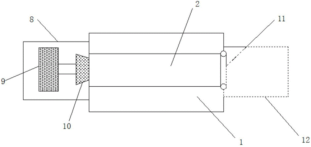
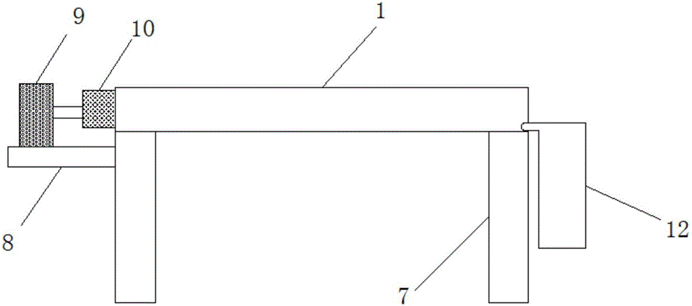
[0015] see Figure 1-3 , the present invention provides a technical solution: a workbench for making clothes, including a platform 1, a support rod 7 is fixedly installed on both sides of the lower end of the platform 1, and a control switch 4 is installed on the outside of the support rod 7. A crossbar 6 is installed in the middle of the support rod 7, a channel 2 is provided in the middle of the platform 1, a first cylinder 5 is installed in the middle of th...


PUM


Abstract

The invention discloses a working table for garment processing. The working table comprises a platform, a first cylinder placed in the middle of the upper end of a level bar, a first top plate connected with the upper end of the first cylinder through a connection bar, the first top plate is placed in an inner cavity of a groove path, a second cylinder is placed in the middle of the upper end of a fixing plate, and a second top plate matched with the groove path is connected with the second cylinder through a connection bar. Both ends of the groove path are provided with one-way valves. By the placement of the fixing plate and the level bar and the installation of the first cylinder and the second cylinder on the fixing plate and the level bar respectively; plus the simple manufacturing of the work table itself, boosts the work efficiency to a high level, saves labor of workers, increases the profits of manufacturers, and maintains the working environment of manufacturers at a qualified standard. The effective separation and classification of waste material from finished products and the divided treatment thereof can save a plurality of processing stages, thus save the salaries for many workers at the same time. All these factors grant the working table certain advantages, and make the working table worthy to be promoted and applied.

Description

technical field [0001] The invention relates to the technical field of clothing workbenches, in particular to a workbench for making clothes. Background technique [0002] At present, my country's production workbench industry is developing rapidly, and there are various devices used for workbenches, but it still faces challenges in many aspects. It is necessary to find solutions that satisfy customers. As we all know, workbenches are an indispensable auxiliary Tools, almost all manufacturers need to use the operating platform. A good working platform can effectively improve the development of the manufacturer, improve the efficiency of the factory, save a lot of labor at the same time, and maintain the environmental sanitation of the manufacturer, which meets the national inspection When it comes to a workbench for garment processing, the existing workbench is relatively simple in design. When workers are working, they often get rubbish everywhere, which is inconvenient to cl...

Claims


Application Information

Patent Timeline
Patent Type & Authority Applications(China)
IPC IPC(8): A41H43/00
CPCA41H43/00
Inventor 王玉婷戚晓楠王荣邵长军
Owner ZHEJIANG DAZUIYA CLOTHING CO LTD
Learn More