
Motor rotor magnetic field sine method, rotor structure, motor and compressor

A technology of motor rotor and rotor structure, applied in the field of electric motors, can solve the problems of deterioration of motor vibration and noise, weakening of fundamental torque, sacrificing magnetic potential, etc. Effect

Active Publication Date: 2017-01-25
GREE ELECTRIC APPLIANCES INC +1
View PDF4 Cites 4 Cited by
  • Summary
  • Abstract
  • Description
  • Claims
  • Application Information

AI Technical Summary

Problems solved by technology

These harmonic components each generate corresponding torque and core loss, which is detrimental to the conversion efficiency of electrical energy into mechanical energy, that is, the operating efficiency of the motor is low. At the same time, the torque generated by the harmonics has a weakening effect on the fundamental torque, and the output force of the motor will be reduced, and at the same time the superposition of harmonic torque of different frequencies will deteriorate the vibration and noise of the motor
At present, there are many optimization schemes for the square wave of air gap magnetic density. For example, an uneven air gap can also form a relatively similar sinusoidal air gap magnetic density waveform, but the air gap is increased and the magnetic potential is sacrificed.

Method used


Image

  • Motor rotor magnetic field sine method, rotor structure, motor and compressor
  • Motor rotor magnetic field sine method, rotor structure, motor and compressor
  • Motor rotor magnetic field sine method, rotor structure, motor and compressor

Examples


Embodiment Construction

[0031] The present invention is described below based on examples, but the present invention is not limited to these examples. In the following detailed description of the invention, some specific details are set forth in detail. The present invention can be fully understood by those skilled in the art without the description of these detailed parts. To avoid obscuring the essence of the present invention, well-known methods, procedures, procedures, and components have not been described in detail.

[0032] Additionally, those of ordinary skill in the art will appreciate that the drawings provided herein are for illustrative purposes and are not necessarily drawn to scale.

[0033] Unless the context clearly requires, throughout the specification and claims, "comprises", "comprises" and similar words should be interpreted in an inclusive sense rather than an exclusive or exhaustive meaning; that is, "including but not limited to" meaning.

[0034] In the description of the ...


PUM


Abstract

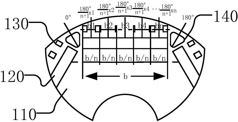
The invention discloses a motor rotor magnetic field sine method, a rotor structure, a motor and a compressor. According to the method, a plurality of magnetic line channels are arranged in the region between a permanent magnet of a motor rotor and the outer circle of an iron core, and the circumferential size of each magnetic force line channel is set, so that the magnetic fields of outer circles of the rotors of the magnetic force line channels can be distributed close to sine. The magnetic force line channels are arranged in the region between the outer circle of the iron core of a motor rotor and a permanent magnet, and the widths of the magnetic force line channels are set according to the sine function, so that the waveform of gap flux density inside the motor of the motor rotor structure can be optimized into a relatively ideal sine curve, and the gap flux density has less low-order harmonic quantity, so that stray loss, electromagnetic noise, vibration and other adverse influences caused by low-order harmonic quantity can be effectively reduced, and the comprehensive operation index of the motor can be promoted. Furthermore, the performance of a compressor and noise and vibration indexes can be improved.

Description

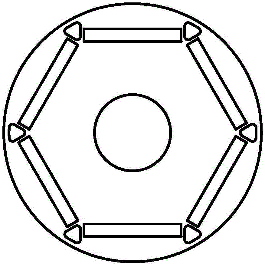
technical field [0001] The invention relates to the technical field of electric motors, in particular to a method for sinusoidalizing the magnetic field of a motor rotor, a rotor structure, a motor and a compressor. Background technique [0002] The motor is mainly composed of a stator and a rotor. The stator and the rotor are of a non-contact type. The conversion of electrical energy into mechanical energy mainly relies on the air gap magnetic field energy between the stator and rotor as the medium. Such as figure 1 As shown, in the permanent magnet motor, the rotor is a permanent magnet structure, and the magnetic field energy of the uniform air gap is usually distributed in a square wave, which contains many harmonic magnetic field energy components, such as figure 2 shown. These harmonic components each generate corresponding torque and core loss, which is detrimental to the conversion efficiency of electrical energy into mechanical energy, that is, the operating effi...

Claims


Application Information

Patent Timeline
Patent Type & Authority Applications(China)
IPC IPC(8): H02K1/27
CPCH02K1/274H02K2201/03H02K2213/03
Inventor 洪飞范少稳
Owner GREE ELECTRIC APPLIANCES INC
Learn More