Cable tray paying-off device

A pay-off device and cable reel technology, which is applied to cable laying equipment and the layout of reels/photosensitive drums, can solve the problems of pickup trucks being unable to transport, increasing difficulty, and occupying space for production vehicles. The effect of improving the quality of pay-off and laying and saving quantity

Active Publication Date: 2017-01-25
STATE GRID SHANDONG ELECTRIC POWER COMPANY WEIFANG POWER SUPPLY +1
View PDF4 Cites 5 Cited by
  • Summary
  • Abstract
  • Description
  • Claims
  • Application Information

AI Technical Summary

Problems solved by technology

[0003] There are several inconveniences in the traditional work: First, the pay-off cone is large in size, about 2m long, and weighs about 300kg, which occupies the space of the production vehicle, and the general pickup cannot be transported, and a double-row truck is required for transportation
The second is that the weight of the cable reel and the pay-off cone is relatively large, requiring the cooperation of multiple people to operate, and there is a greater safety risk when erecting the pay-off cone and the cable reel
The third is that there are many types of control cables, and the different volumes of the cable reels increase the difficulty of combining the pay-off cone and the cable reel
The fourth is that two people need to stay at the cable reel to operate when the cable is released
[0004] Since there is no special cable reel payout tool at present, the above problems have been difficult to solve

Method used


Image

  • Cable tray paying-off device
  • Cable tray paying-off device
  • Cable tray paying-off device

Examples


Embodiment Construction

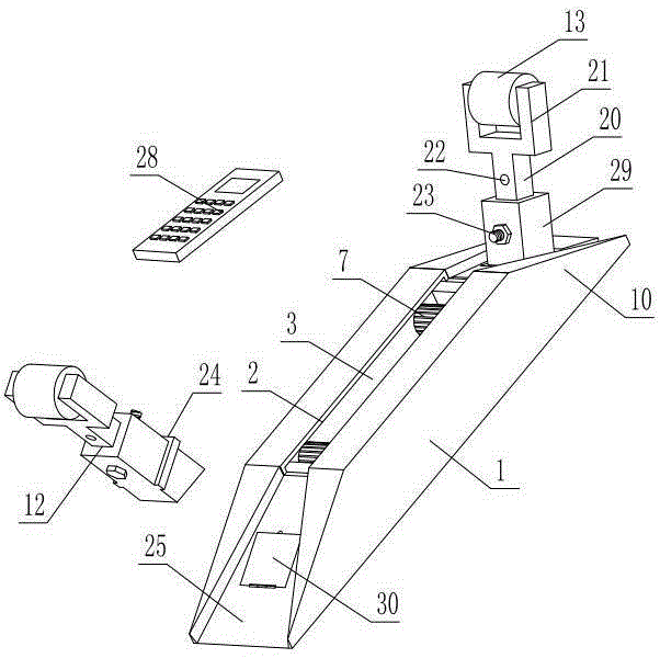
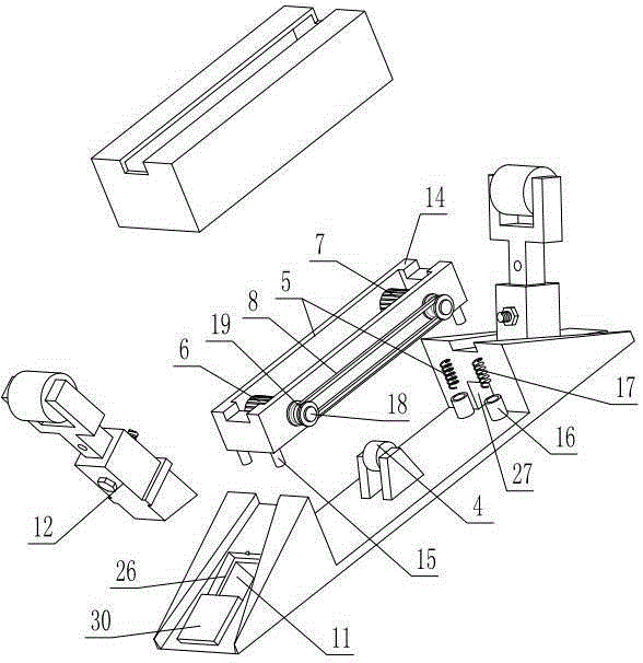
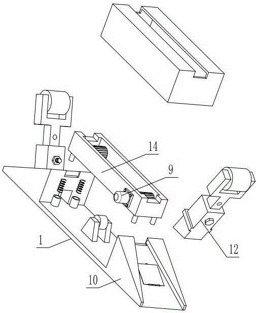
[0025]As shown in the figure, the cable reel pay-off device includes a base 1, the upper part of the base is provided with a groove 2 extending forward and backward along the length of the base, the base is provided with a cavity 3 communicating with the groove, and the middle part of the cavity is Load bearing wheels 4 are installed in the rotating shaft extending left and right, and front drive wheels 6 and rear drive wheels 7 are respectively installed at the front and rear ends of the load wheels by positioning device 5 in the cavity. The top of the outer periphery of the load-bearing wheel is slightly higher, and the front drive wheel and the rear drive wheel are driven and matched by a belt 8, and a motor 9 matched with the front drive wheel is also installed in the cavity, and an inclined platform 10 is fixed at the front and rear ends of the base respectively. , the inclined platform is provided with a through-hole 11 that runs up and down, and a positioning rod 12 is i...


PUM


Abstract

The invention discloses a cable tray paying-off device. The cable tray paying-off device comprises a base. A groove extending back and forth along the length direction of the base is arranged in the upper portion of the base, a cavity communicated with the groove is arranged in the base, a carrying roller is mounted in the middle portion of the cavity through a rotating shaft extending left and right, a front driving wheel and a back driving wheel are respectively mounted at the front end and the back end of the carrying roller in the cavity through a positioning device, the outer periphery top of each of the front driving wheel and the back driving wheel is slightly higher than that of the carrying roller, the front driving wheel is in transmission fit with the back driving wheel through a belt, a motor in transmission fit with the front wheel is further mounted in the cavity, the front and back ends of the base is respectively provided with a sloping desk, each of the sloping desks is provided with a vertically-penetrating through hole, a positioning rod is inserted in the through hole, and a roller is mounted at the upper end of the positioning rod. The cable tray feeding device is reasonable in structure, free from overturning of a cable tray, capable of realizing paying off by only rolling the cable tray and simple and laborsaving in operation, at most one person is enough to stay with the cable tray during paying off, and paying-off efficiency can be greatly improved.

Description

technical field [0001] The invention relates to a cable reel pay-off device. Background technique [0002] The control cable laying workload is relatively large in substation infrastructure construction and technical transformation work. The conventional laying method is to use the pay-off cone to lay the wires manually, that is, first erect the cable reel (that is, in a rollable state), manually carry the pay-off cone into the center hole of the cable reel, and then erect the two as a whole, so that the cable reel Put it horizontally on the pay-off cone (if the weight of the cable reel is heavy, such as about 2 tons, this step requires a crane to pass the cable reel on the pay-off cone), and then manually drag the cable to lay the cable. [0003] There are several inconveniences in the traditional work: First, the pay-off cone is large in size, about 2m long and about 300kg in weight, which occupies the space of the production vehicle and cannot be transported by general p...

Claims


Application Information

Patent Timeline
IPC IPC(8): H02G1/06H02G11/02
Inventor 孙延栋徐克政刘继君杨晶晶王敬海王嘉雨张凡张以宁王鑫冯江霞
Owner STATE GRID SHANDONG ELECTRIC POWER COMPANY WEIFANG POWER SUPPLY
Why Eureka
Try Eureka