
Medium waveguide crack array antenna with series feed of metal hollow waveguide

A technology of waveguide feeding and array antenna, which is applied in the direction of slot antenna, antenna, antenna array, etc., can solve the problems of large loss, complex processing and welding process, large weight and size of metal hollow waveguide slot array antenna, etc., and achieve low loss , Improve the effect of surface utilization

Pending Publication Date: 2017-01-25
成都雷电微力科技股份有限公司
View PDF5 Cites 3 Cited by
  • Summary
  • Abstract
  • Description
  • Claims
  • Application Information

AI Technical Summary

Problems solved by technology

[0004] One is that the weight and size of the existing metal hollow waveguide slot array antenna are large, the processing and welding processes are complicated, and the cost is high; The feed network in the structure needs to occupy part of the area, resulting in a small effective radiation area. A dielectric slot array antenna that uses a metal hollow waveguide as the feed network to reduce feed loss and increase the effective area of ​​the effective radiation area is provided.

Method used


Image

  • Medium waveguide crack array antenna with series feed of metal hollow waveguide
  • Medium waveguide crack array antenna with series feed of metal hollow waveguide
  • Medium waveguide crack array antenna with series feed of metal hollow waveguide

Examples


Embodiment 1

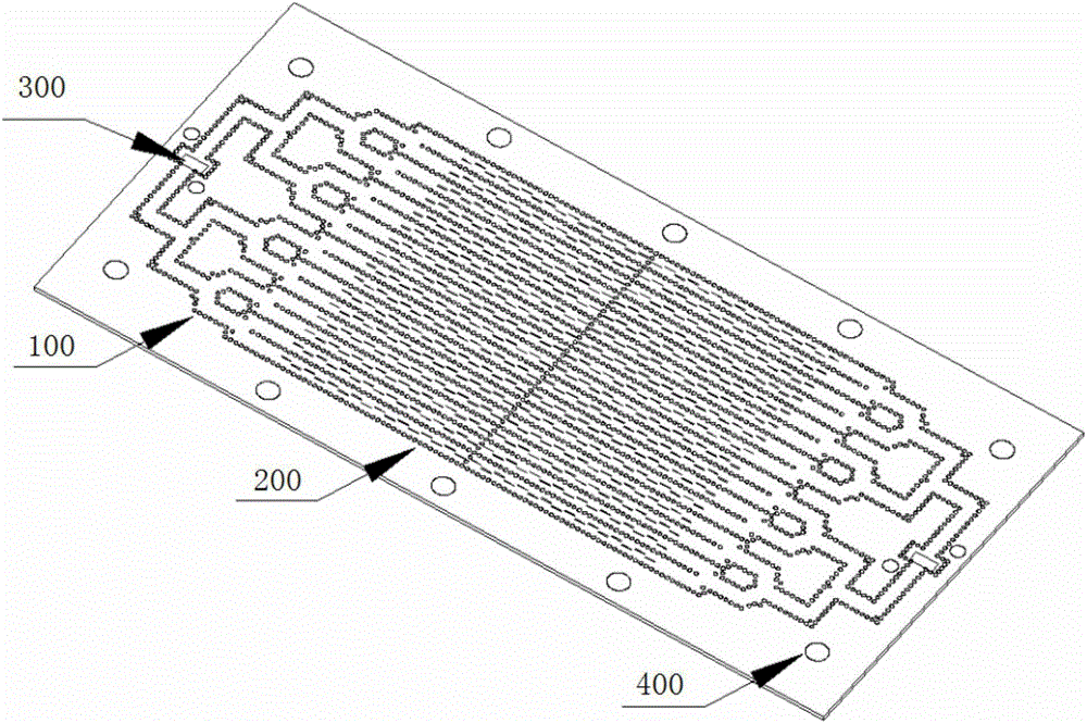
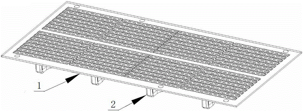
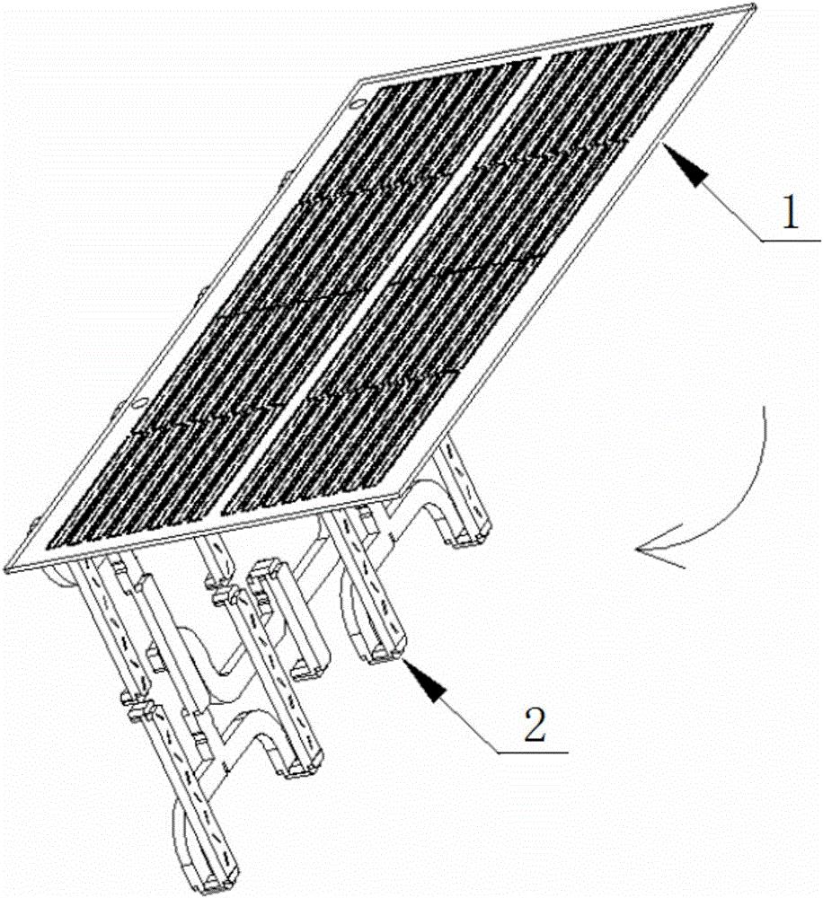
[0035] Embodiment 1: as figure 2 As shown, this embodiment provides a metal hollow waveguide feeding slot array antenna, including an antenna dielectric layer 1 and a metal hollow waveguide feeding device 2;

[0036] The antenna dielectric layer 1 includes an antenna radiation slot structure 11 and an antenna feeding slot structure 12 ; the antenna dielectric layer 1 is connected to the metal hollow waveguide feeding device 2 through the antenna feeding slot structure 12 . The antenna dielectric layer 1 is a substrate made of a common antenna dielectric material, which is used to allow electromagnetic waves to propagate therein; the radiation slots in the antenna radiation slot structure 11 and the feed slots in the antenna feed slot structure 12 are all according to the predetermined Arranged in a set way, generally, such as Figure 4a , Figure 4c As shown, the antenna feeding slot structure 12 forms an antenna feeding slot surface 15 on one surface (the following surface...


PUM


Abstract

The invention relates to the technical field of antenna designs and particularly relates to a medium waveguide crack array antenna with series feed of a metal hollow waveguide. According to the medium waveguide crack array antenna, the metal hollow waveguide is used as a crack array antenna of a feed device; compared with a traditional medium waveguide feed manner, a feed manner adopted by the invention has small loss; meanwhile, the metal hollow waveguide feed device does not adopt a traditional plane feed manner, and the feed device is independently arranged and is fixed with upper and lower layers of an antenna medium layer, so that a feed line does not occupy a surface area of the medium layer, and furthermore, the surface of the medium layer can be used for arranging antenna radiation cracks and the surface utilization rate of the medium layer is greatly improved.

Description

technical field [0001] The invention relates to the technical field of antenna design, in particular to a dielectric waveguide slot array antenna fed in series by a metal hollow waveguide. Background technique [0002] The waveguide slot array antenna is widely used in radar and communication systems due to its high efficiency, simple design, and easy realization of low sidelobes, but its weight and size are large, and the processing and welding processes are complicated, especially when it reaches the millimeter wave frequency band. , the waveguide crack array has higher and higher requirements on the welding process as the frequency increases, resulting in a substantial increase in cost. In order to overcome these difficulties, in recent years, the use of dielectric substrates to realize slot array antennas (that is, dielectric waveguide slot arrays) has gradually become the mainstream. In this method, the antenna adopts PCB processing technology, and the cost, weight, siz...

Claims


Application Information

Patent Timeline
IPC IPC(8): H01Q21/00H01Q13/10
CPCH01Q13/106H01Q21/0006
Inventor 丁卓富管玉静肖润均
Owner 成都雷电微力科技股份有限公司
Learn More