x-ray tube
An X-ray and ball tube technology, applied in the X-ray field, can solve the problems of thin-wall shaft 41 fracture, complicated manufacturing process, and reduce the thickness of thin-wall shaft 41, so as to achieve the effects of reducing temperature conduction and strengthening strength
- Summary
- Abstract
- Description
- Claims
- Application Information
AI Technical Summary
Problems solved by technology
Method used
Image
Examples
Embodiment 1
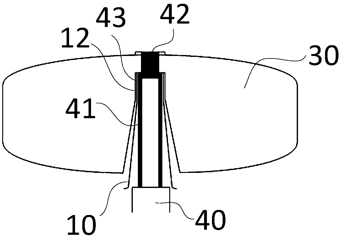
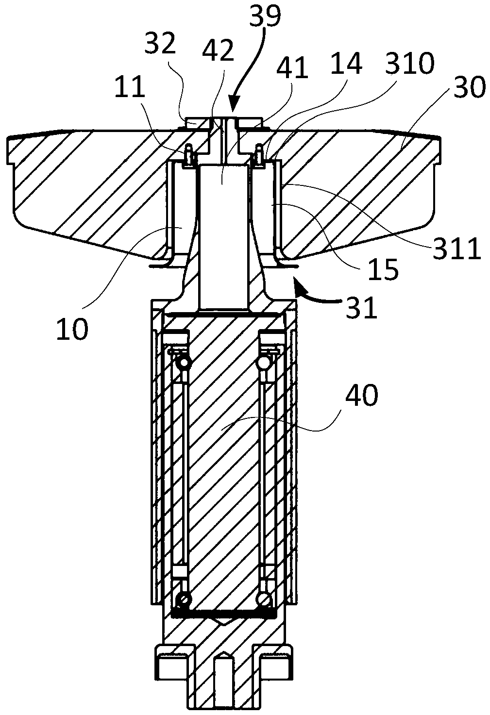
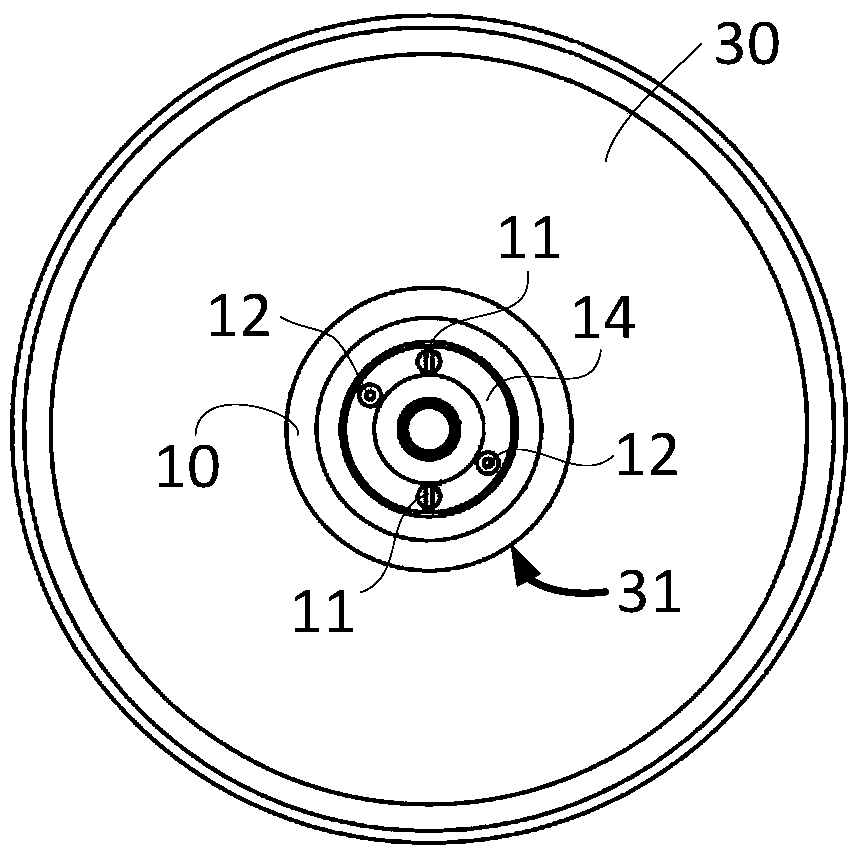
[0027] figure 2 is a schematic vertical sectional view of the target disk according to the first embodiment. Such as figure 2 As shown, the X-ray tube provided in this embodiment includes a target disc and a rotating part that drives the target disc to rotate, wherein the target disc 30 includes a target surface that can generate X-rays under the impact of electrons, and the The target plate 30 is also defined with a positioning groove 31 on its central axis on the opposite side to the target surface, so that when the rotating portion 40 is fixed to the target plate 30, the positioning groove 31 is aligned with the rotating portion 40 An annular space is defined between the circumferential side walls of the rotating part 40 and the target disc 30 is also provided with a heat-resistant plate 10, and the heat-resistant plate 10 is fixed to the target disc 30 within the annular space. superior.
[0028] High-speed electrons impact on the target surface of the target disk 30 ...
Embodiment 2
[0035] Figure 4 is a schematic vertical sectional view of the target disk according to the second embodiment. Such as Figure 4 As shown, the connection mode and shape of the rotating part 40 and the target disk 30 in this embodiment are basically the same as those in Embodiment 1, and will not be repeated here. Different from Embodiment 1, at least two layers of heat-resisting plates 10 are used in this embodiment. Taking the use of two-layers of heat-resisting plates 10 as an example, the heat-resisting plate 10 close to the thin-walled shaft 41 is the inner heat-resisting plate 10a, far away from the thin-walled The heat shield 10 of the shaft 41 is an outer heat shield 10b. The outer heat-resisting plate 10b has a diameter larger than that of the inner heat-resisting plate 10a, and respectively includes a substantially flat fixed portion and a heat-resistant portion extending angularly from the fixed portion.
[0036] Figure 5 is a schematic diagram of the installati...
Embodiment 3
[0043] Image 6 is a schematic vertical cross-sectional view of a target disk according to the third embodiment. Such as Image 6 As shown, the X-ray tube according to this embodiment includes a target disc 30 that generates X-rays 60 under the impact of electrons 50, and a rotating part 40 that drives the target disc 30 to rotate. The target disc 30 includes a metal material The first part 35 constituted and the second part 32 constituted by heat capacitive material, the rotating part 40 is connected to the first part 35 of the target disk 30, and a heat shield 10 is arranged between the target disk 30 and the rotating part 40, so The heat shield 10 is fixed on the first portion 35 of the target disk 30 .
[0044] On the upper surface of the first part 35, on the position of electron bombardment, a high-temperature heat-resistant layer 34 is provided. The high-temperature heat-resistant layer 34 is the position directly bombarded by electrons, and the temperature is the hig...
PUM
 Abstract
Description
Claims
Application Information
 - R&D Engineer
- R&D Manager
- IP Professional
- Industry Leading Data Capabilities
- Powerful AI technology
- Patent DNA Extraction
Browse by: Latest US Patents, China's latest patents, Technical Efficacy Thesaurus, Application Domain, Technology Topic, Popular Technical Reports.
© 2024 PatSnap. All rights reserved.Legal|Privacy policy|Modern Slavery Act Transparency Statement|Sitemap|About US| Contact US: help@patsnap.com


