
Method for calibrating laser light sources and imaging spectrometers in on-orbit manner

A laser light source and imaging spectrum technology, applied in the field of imaging spectrometer on-board calibration, can solve problems such as chemical composition and bandwidth error, calibration error, etc., to reduce difficulty, avoid changes in bidirectional reflectivity, and avoid errors. Effect

Active Publication Date: 2017-01-25
CHANGCHUN INST OF OPTICS FINE MECHANICS & PHYSICS CHINESE ACAD OF SCI
View PDF4 Cites 16 Cited by
  • Summary
  • Abstract
  • Description
  • Claims
  • Application Information

AI Technical Summary

Problems solved by technology

[0005] In order to solve the above-mentioned technical problems, the present invention provides a laser light source and an imaging spectrometer on-board calibration method to solve the problems caused by the ultraviolet components in the sunlight decomposing the chemical composition and bandwidth of the surface of the diffuse reflection plate and the calibration error of the center wavelength. Problems causing on-board calibration errors of the imaging spectrometer

Method used


Image

  • Method for calibrating laser light sources and imaging spectrometers in on-orbit manner
  • Method for calibrating laser light sources and imaging spectrometers in on-orbit manner
  • Method for calibrating laser light sources and imaging spectrometers in on-orbit manner

Examples


Embodiment Construction

[0034] The following will clearly and completely describe the technical solutions in the embodiments of the present invention with reference to the accompanying drawings in the embodiments of the present invention. Obviously, the described embodiments are only some, not all, embodiments of the present invention. Based on the embodiments of the present invention, all other embodiments obtained by persons of ordinary skill in the art without making creative efforts belong to the protection scope of the present invention.

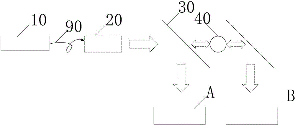
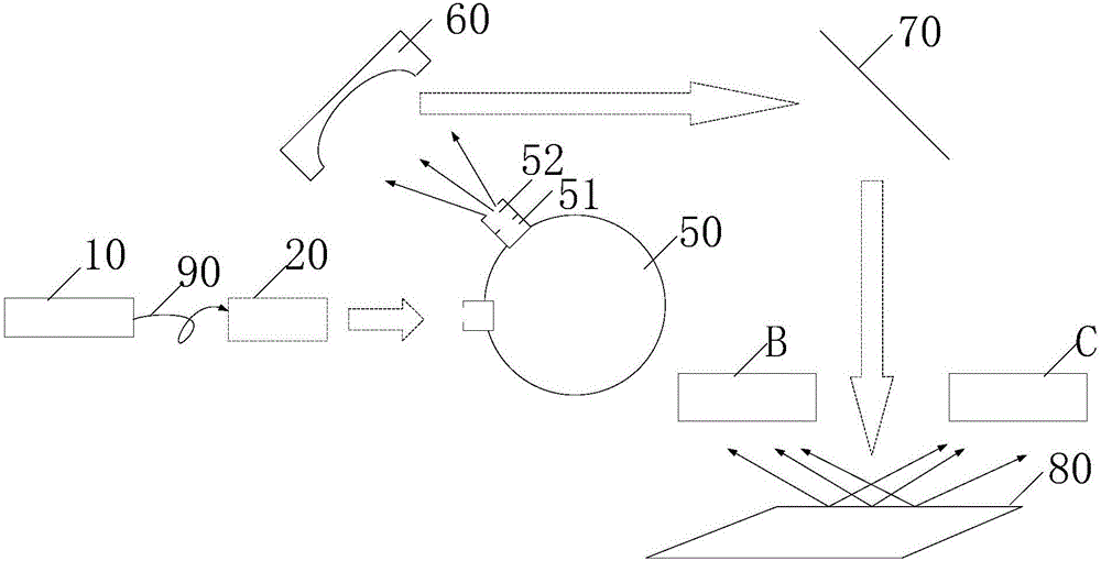
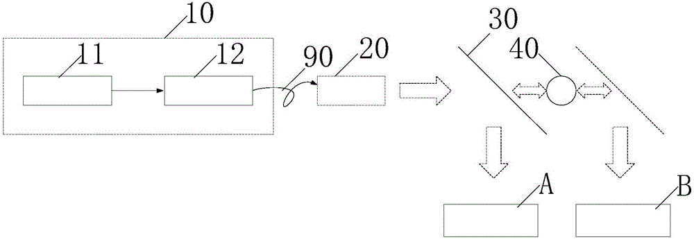
[0035] The embodiment of the present application provides a laser light source, which is applied to on-board calibration of imaging spectrometers, as shown in Figure 1(a) and Figure 1(b), including: a laser 10, an optical fiber 90, a collimating lens group 20, A reflection mirror 30, motor 40, integrating sphere 50, collimation system 60, second reflection mirror 70 and diffuse reflection plate 80; Wherein,

[0036] The optical fiber 90 is used to transmit the...


PUM


Abstract

The invention discloses a method for calibrating laser light sources and imaging spectrometers in an on-orbit manner. Each laser light source comprises a laser device, an optical fiber, a collimating lens assembly, a first reflecting mirror, a motor, an integrating sphere, a collimating system, a second reflecting mirror and a diffuse reflector. The method has the advantages that collimated laser light can be provided by the laser light sources for space low-temperature radiometers and transmission radiometers, and accordingly the transmission radiometers can be calibrated by the aid of the space low-temperature radiometers; monochromatic surface light sources with uniform radiant brightness further can be provided by the laser light sources for the transmission radiometers and the imaging spectrometers, so that the imaging spectrometers can be calibrated in the on-orbit manner by the aid of transmission radiometers; the laser light sources do not contain ultraviolet components, accordingly, chemical compositions of the surfaces of the diffuse reflectors can be prevented from being decomposed, and on-orbit calibration errors of the imaging spectrometers due to change of bidirectional reflectivity of the diffuse reflectors can be prevented; the monochromatic light sources are high in wavelength calibration precision, and accordingly the calibration precision of the imaging spectrometers can be improved.

Description

technical field [0001] The present application relates to the technical field of on-board calibration of imaging spectrometers, and more specifically, relates to a laser light source and an on-board calibration method of imaging spectrometers. Background technique [0002] With the development of scientific research, especially in the field of national economy, research on crop yield estimation, mineral exploration, resource survey, environmental monitoring and other issues requires high-precision hyperspectral remote sensing data. Hyperspectral Remote Sensing (HyperspectralRemoteSensing), the full name of hyperspectral resolution remote sensing, refers to the continuous remote sensing imaging of ground objects with a narrow and continuous spectral channel. The most important imaging device is the imaging spectrometer, so the imaging spectrometer On-board calibration accuracy greatly affects the imaging effect of hyperspectral remote sensing. [0003] In the prior art, the ...

Claims


Application Information

Patent Timeline
Patent Type & Authority Applications(China)
IPC IPC(8): G01J3/10G01J3/28G02B27/09
CPCG01J3/10G01J3/2823G01J2003/2866G02B27/0916G02B27/0927
Inventor 叶新孙立微王玉鹏方伟
Owner CHANGCHUN INST OF OPTICS FINE MECHANICS & PHYSICS CHINESE ACAD OF SCI
Learn More