Hoisting mounting method and hoisting mounting fixture for torsional vibration damper

A technology for torsional vibration dampers and installation tooling, which is applied in the directions of transportation and packaging, load hanging components, etc., can solve the problem of reducing the installation efficiency of torsional vibration dampers, increasing the difficulty of assembly, and difficult to install holes for torsional vibration dampers. Aligning the through hole of the crankshaft, etc., to achieve the effect of simple and easy lifting and installation method, improve installation efficiency, and ensure lifting safety

Inactive Publication Date: 2017-01-25
CSSC MARINE POWER
View PDF7 Cites 0 Cited by
  • Summary
  • Abstract
  • Description
  • Claims
  • Application Information

AI Technical Summary

Problems solved by technology

In the prior art, the hoisting wire rope is directly used to wind the silicone oil shock absorber shell for a week to lift vertically. This vertical lifting method has a major safety hazard of the lifting wire rope slipping off. In the circumferential direction of the shell, it is also difficult to rotate the silicone oil shock absorber shell in a small amount, which makes it difficult for the multiple mounting holes of the torsional vibration damper to align with the multiple crankshaft through holes of the crankshaft end, which increases the difficulty of assembly. Reduced torsional vibration damper installation efficiency

Method used


Image

  • Hoisting mounting method and hoisting mounting fixture for torsional vibration damper
  • Hoisting mounting method and hoisting mounting fixture for torsional vibration damper
  • Hoisting mounting method and hoisting mounting fixture for torsional vibration damper

Examples


Embodiment Construction

[0032] The present invention will be further described below in conjunction with drawings and embodiments.

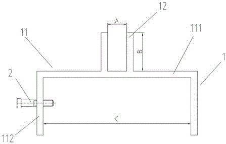
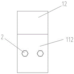
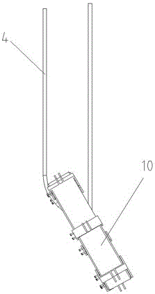
[0033] Such as figure 1 with figure 2 As shown, the torsional vibration damper lifting installation tooling of the present invention includes 6 lifting brackets 1 uniformly fixed on the circumferential edge of the torsional vibration damper 10 and 2 fastening screws 2 fixed on one side of the bracket, lifting The bracket 1 is a welded part in a convex shape, including a groove-shaped lower clamping seat 11 and a pair of lifting wire rope splints 12 vertically extending upward from the upper longitudinal middle of the lower clamping seat 11. The lower clamping seat 11 includes a fixed and integrated The upper top board 111 and the lower side boards 112 on both sides. The lower clamp seat 11 is clamped on the edge of the torsional vibration damper 10 in the circumferential direction, and the ends of at least two fastening screws 2 respectively pass through a lower side...


PUM


Abstract

The invention discloses a hoisting mounting fixture for a torsional vibration damper. The hoisting mounting fixture comprises a plurality of hoisting supports and at least two fastening screws, each hoisting support is in a T shape and comprises a lower clamping seat and a pair of hoisting steel wire rope clamping plates upwardly and vertically extending from the longitudinal upper middle of the lower clamping seat, each lower clamping seat clamps the peripheral edge of the torsional vibration damper, and ends of the fastening screws respectively penetrate one side of each lower clamping seat to be abutted against the lateral side of the outer edge of the torsional vibration damper. A hoisting mounting method includes the steps: 1) hoisting the torsional vibration damper in horizontal arrangement; 2) mounting the hoisting supports; 3) vertically hoisting the torsional vibration damper; 4) aligning a center hole of the torsional vibration damper to a mounting flange of a crankshaft end face; 5) pulling the torsional vibration damper to sleeve the mounting flange of the crankshaft end face; 6) fixing the torsional vibration damper to the crankshaft end. The hoisting mounting fixture guarantees hoisting safety, the hoisting mounting method is simple, easy and feasible, mounting efficiency is improved, and the problem of inconvenience in mounting of the torsional vibration damper due to lack of hoisting holes is solved.

Description

technical field [0001] The invention relates to a lifting and installing tool for marine low-speed diesel engine parts, especially a lifting and installing tool for a torsional vibration damper, and also relates to a method for lifting and installing the torsional vibration damper on the end of a crankshaft, which belongs to special tools for lifting technology field. Background technique [0002] The torsional vibration damper is an important part used to eliminate the torsional vibration of the diesel engine. During the operation of the diesel engine, if there is a problem of excessive torsional vibration, it will cause adverse effects such as the movement of the main shaft and unstable speed regulation of the main engine. Vibration dampers to eliminate torsional vibrations. [0003] When the diesel engine is installed and debugged in the factory, it is sometimes necessary to install a torsional vibration damper at the end of the crankshaft. The commonly used torsional vi...

Claims


Application Information

Patent Timeline
Patent Type & Authority Applications(China)
IPC IPC(8): B66C1/10
CPCB66C1/10
Inventor 车路
Owner CSSC MARINE POWER
Why Eureka
Try Eureka