
Pillar Preform Forming Die

A technology for forming molds and preforms, applied in the field of forming molds for post preforms of composite post insulators, can solve problems such as product delamination, cracks and air bubbles, and low yield, and achieve simple and quick flipping methods and finished products The effect of high efficiency and convenient operation

Active Publication Date: 2018-11-13
北京玻钢院复合材料有限公司
View PDF6 Cites 0 Cited by
  • Summary
  • Abstract
  • Description
  • Claims
  • Application Information

AI Technical Summary

Problems solved by technology

The above-mentioned molds can improve casting efficiency and molding quality, but still cannot solve the problems of product delamination, cracks and air bubbles, and the yield rate is still not high

Method used


Image

  • Pillar Preform Forming Die
  • Pillar Preform Forming Die
  • Pillar Preform Forming Die

Examples


Embodiment 1

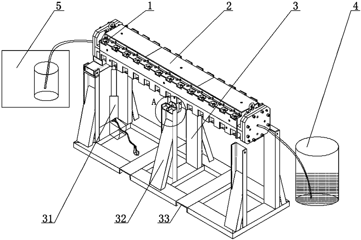
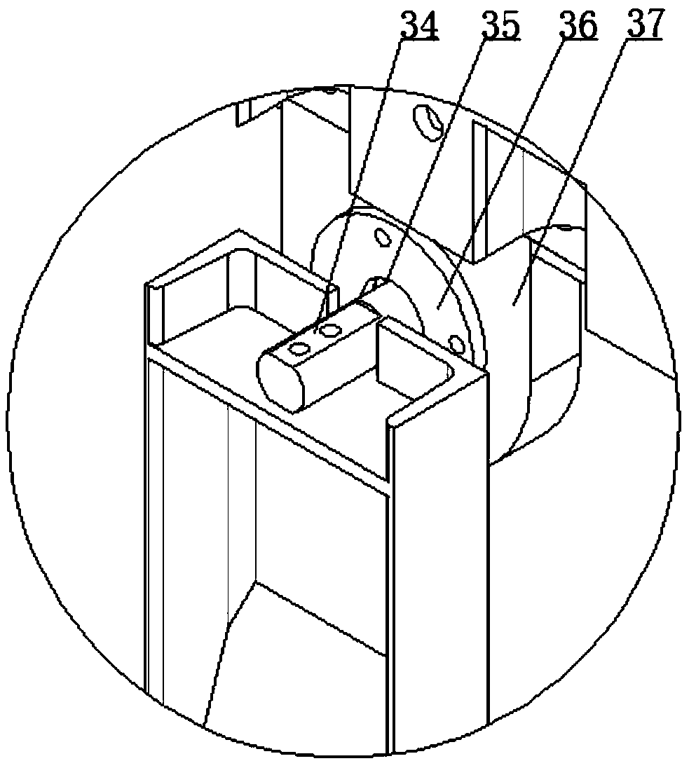
[0031] figure 1 It is a structural schematic diagram of a pillar preform molding die of the present invention. Depend on figure 1 It can be seen that the forming mold of the present invention includes a forming main unit 1 , a heating unit 2 , a tilting unit 3 , a pressurizing unit 4 and a vacuuming unit 5 .

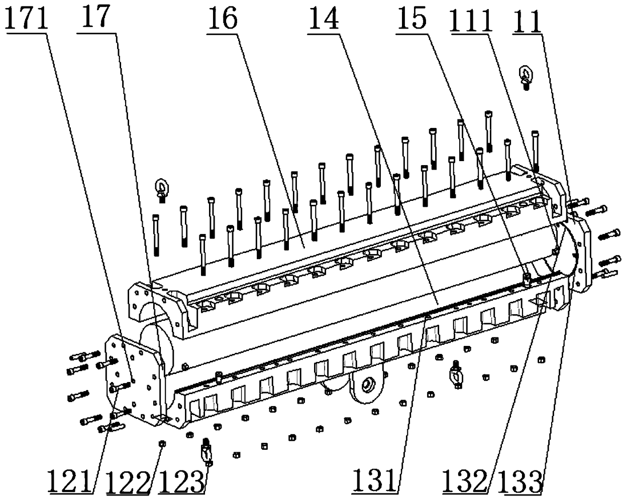
[0032] image 3It is a structural schematic diagram of the molding main unit of the molding die of the present invention. Figure 4 It is a structural schematic diagram of the glue inlet end cap of the present invention. The forming body unit 1 includes an upper forming die 16, a lower forming die 14, a glue inlet end cap 17 and a glue outlet end cap 11; these parts cooperate with each other to form a cavity for receiving a post insulator mandrel with a reinforcing fiber layer . The glue inlet end cover 17 is provided with a glue inlet 171 , and the pressurizing unit 4 communicates with the cavity of the molding main unit 1 through the glue inlet 171 . The glue out...

Embodiment 2

[0039] Except that the heating unit 2 is replaced by a thermal oil circulation heating unit, other components are the same as in Embodiment 1. The metal bodies of the forming upper die 16 and the forming lower die 14 are provided with a plurality of holes that communicate with each other, and the hot oil circulates in the holes, and the heating is realized through the circulation of the hot oil.


PUM

PropertyMeasurementUnit
widthaaaaaaaaaa
heightaaaaaaaaaa
diameteraaaaaaaaaa

Abstract

The invention discloses a forming mold of a support column prefabricated body. The forming mold comprises a forming main body unit, a turning inclination unit, a pressurizing unit and a vacuuming unit, wherein the forming main body unit comprises an upper forming mold, a lower forming mold, a glue inlet end cover and a glue outlet end cover which are matched with one another to form a cavity; the cavity is used for containing a support column insulator core rod with a reinforcing fiber layer; the turning inclination unit is arranged below the forming main body unit and is used for adjusting the working position of the forming main body unit to be inclined or horizontal; the pressurizing unit is communicated with the cavity of the forming main body unit and is used for supplying resin to the cavity for containing the support column insulator core rod with the reinforcing fiber layer; the vacuuming unit is communicated with the cavity of the forming main body unit and is used for promoting the resin to immerse into the reinforcing fiber layer. By adopting the forming mold disclosed by the invention, the phenomena such as layering, cracking and bubbling of a product can be remarkably reduced, and the finished product rate can be high.

Description

technical field [0001] The invention relates to a mold for forming a pillar preform, in particular to a mold for forming a pillar preform of a composite pillar insulator. Background technique [0002] The existing large-diameter pillar insulator mandrel generally adopts the process of winding glass fibers soaked in epoxy resin and then curing and molding. The above process is prone to delamination and air bubbles, and at the same time, it is prone to cracks after curing shrinkage. This results in products that fail to meet standard electrical and mechanical performance requirements, resulting in lower yields. Both the molding process and the molding die affect the yield, and sometimes the molding die has a greater impact. CN102886851A discloses a three-pillar insulator casting mold, which includes a left mold and a right mold; the center of the mold cavity is a spherical surface and a central conductor is installed; three pillars protrude from the center spherical surface ...

Claims


Application Information

Patent Timeline
Patent Type & Authority Patents(China)
IPC IPC(8): B29C70/48B29C33/02
CPCB29C33/02B29C70/48
Inventor 南无疆张雄军郝春功胡平陈铃飞耿树军
Owner 北京玻钢院复合材料有限公司
Learn More