Jacking mechanism for thyristor valve

A thyristor string, top pressure technology, applied in electrical components, semiconductor/solid state device manufacturing, circuits, etc., can solve the problems of high precision gap gasket thickness, difficult assembly of thyristor valve strings, and misalignment of thyristor valve strings. Electrical performance requirements, improving reliability and stability, and stable hydraulic pressure

Pending Publication Date: 2017-01-11
GLOBAL ENERGY INTERCONNECTION RES INST CO LTD +3
View PDF4 Cites 1 Cited by
  • Summary
  • Abstract
  • Description
  • Claims
  • Application Information

AI Technical Summary

Problems solved by technology

[0003] At present, the top pressure mechanism of the thyristor valve in the power electronic device is a component force top pressure structure in which a plurality of bolts apply force respectively for top pressure, or a hydraulic top pressure structure in which the hydraulic top pressure is filled with gaskets to apply force; the former requires manual Tightening several bolts separately makes it very difficult to operate when applying force, and it is also easy to cause misalignment and deflection of the thyristor valve string during operation, which causes great difficulties in the assembly of the thyristor valve string; although the latter realizes automatic hydraulic top pressure , but it needs to be equipped with gap gaskets of different thicknesses to maintain the pressure of the disc spring. The thickness accuracy of the gap gaskets is also very high, and the actual press-fitting operation is time-consuming and laborious.

Method used


Image

  • Jacking mechanism for thyristor valve
  • Jacking mechanism for thyristor valve
  • Jacking mechanism for thyristor valve

Examples


Embodiment Construction

[0034] The following will clearly and completely describe the technical solutions in the embodiments of the present invention with reference to the accompanying drawings in the embodiments of the present invention. Obviously, the described embodiments are only some, not all, embodiments of the present invention. Based on the embodiments of the present invention, all other embodiments obtained by persons of ordinary skill in the art without making creative efforts fall within the protection scope of the present invention.

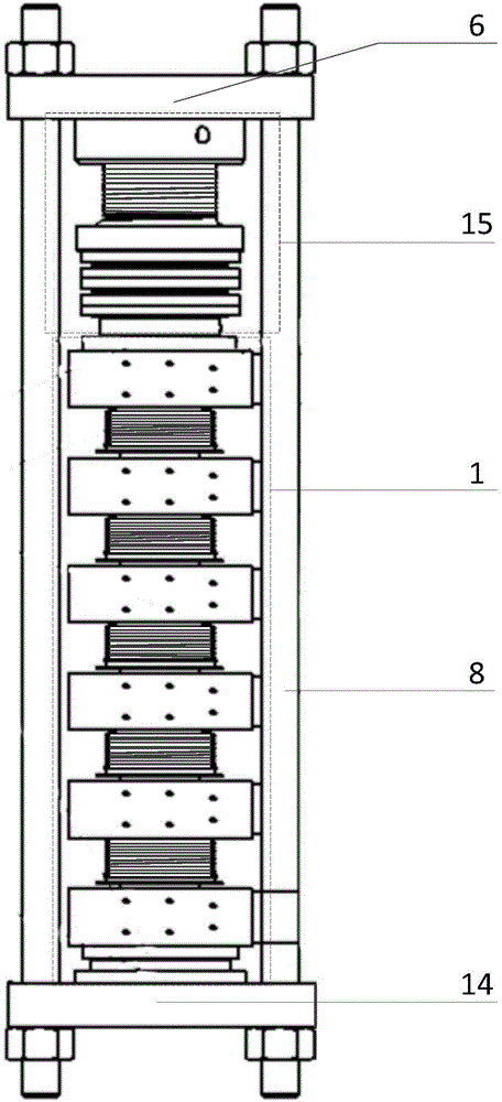
[0035] Such as figure 1 As shown, the present invention provides a pressing mechanism for a thyristor valve, which includes an upper end plate 6 and a pressing assembly 15 arranged between the upper end plate 6 and the thyristor string 1;

[0036] The upper end plate 6 is connected with the lower end plate 14 at the bottom of the thyristor string 1 by a vertically arranged insulating screw 8 .

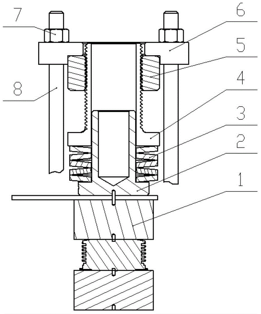
[0037] Such as figure 2 As shown, the pressing assembly 15 i...


PUM


Abstract

The invention provides a jacking mechanism for a thyristor valve. The jacking mechanism comprises an upper end plate, a guiding jacking column which is arranged between the upper end plate and a thyristor string, and a disc spring group and a screw thread self-locking jacking rod which are arranged on the guiding jacking column in sequence, wherein a screw thread self-locking nut which is matched with the screw thread self-locking jacking rod is arranged on the screw thread self-locking jacking rod in a sleeving manner; and the upper end plate is connected with the screw thread self-locking jacking rod and clamped with the screw thread self-locking nut. The jacking mechanism provided by the invention can bear pressure-mounting force of higher than 200KN; the jacking mechanism is convenient to apply pressure-mounting force, stable and reliable in applying hydraulic force, simple and convenient to operate manually, and capable of satisfying vertical and concentric assembling precision requirement of the thyristor valve string; requirement on the alignment precision of the thyristor valve string is greatly improved; the jacking mechanism is capable of satisfying different pressure-mounting force requirements of the thyristor valve string of different pressure-mounting force; the assembling reliability and stability of the thyristor valve string are improved; and the electrical performance requirement of the thyristor valve for a high-voltage high-current high-capacity power electronic apparatus can be well satisfied.

Description

technical field [0001] The invention relates to a thyristor valve accessory, in particular to a pressing mechanism for a thyristor valve. Background technique [0002] With the rapid development of power electronics technology, power electronic devices based on thyristors are more and more widely used in power systems. Therefore, the capacity of the thyristor-based power electronic device, that is, the thyristor valve, is also increasing; with the continuous increase of the thyristor flow capacity, and at the same time, the external dimensions of the thyristor are also increasing, and the required top pressure is also increasing. Therefore, the requirements for press-fitting are becoming more and more stringent, especially for large-size thyristors and their high-voltage thyristor valves, the valve string pressing mechanism is required to be safe, reliable, stable in performance, high in centering accuracy and easy to install. [0003] At present, the top pressure mechanism...

Claims


Application Information

Patent Timeline
IPC IPC(8): H01L21/687
CPCH01L21/68721H01L21/6875H01L21/68771H01L21/68785
Inventor 刘智刚张雷赵东元乔尔敏蔡博廖福旺陈金祥游浩叶兆平
Owner GLOBAL ENERGY INTERCONNECTION RES INST CO LTD
Why Eureka
Try Eureka