
Color electronic paper, display device and display method

A display method and electronic paper technology, applied in static indicators, instruments, nonlinear optics, etc., can solve problems such as color shift, and achieve the effects of simplifying structure, improving display effect, and eliminating color shift problems.

Inactive Publication Date: 2017-01-11
BOE TECH GRP CO LTD +1
View PDF0 Cites 5 Cited by
  • Summary
  • Abstract
  • Description
  • Claims
  • Application Information

AI Technical Summary

Problems solved by technology

When the color electronic paper displays the color of charged particles with a higher threshold voltage, a voltage is applied to the upper electrode and the lower electrode so that the voltage difference between the upper electrode and the lower electrode meets the threshold voltage of the charged particles with a higher threshold voltage. Both the charged particles with high threshold voltage and the charged particles with low threshold voltage are driven from the lower substrate to the upper substrate, and in order to realize the monochrome display of charged particles with higher threshold voltage, it is necessary to apply a reverse voltage to the upper electrode and the lower electrode to The charged particles with a low threshold voltage are returned to the lower substrate, but since the charged particles with a higher threshold voltage are located on the upper side of the display area of ​​the color electronic paper, and the charged particles with a lower threshold voltage are located on the lower side of the display area of ​​the color electronic paper, different Layered arrangement of charged particles of color, causing color shift problems

Method used


Image

  • Color electronic paper, display device and display method
  • Color electronic paper, display device and display method
  • Color electronic paper, display device and display method

Examples


Embodiment 1

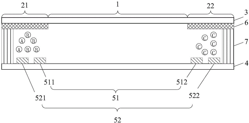
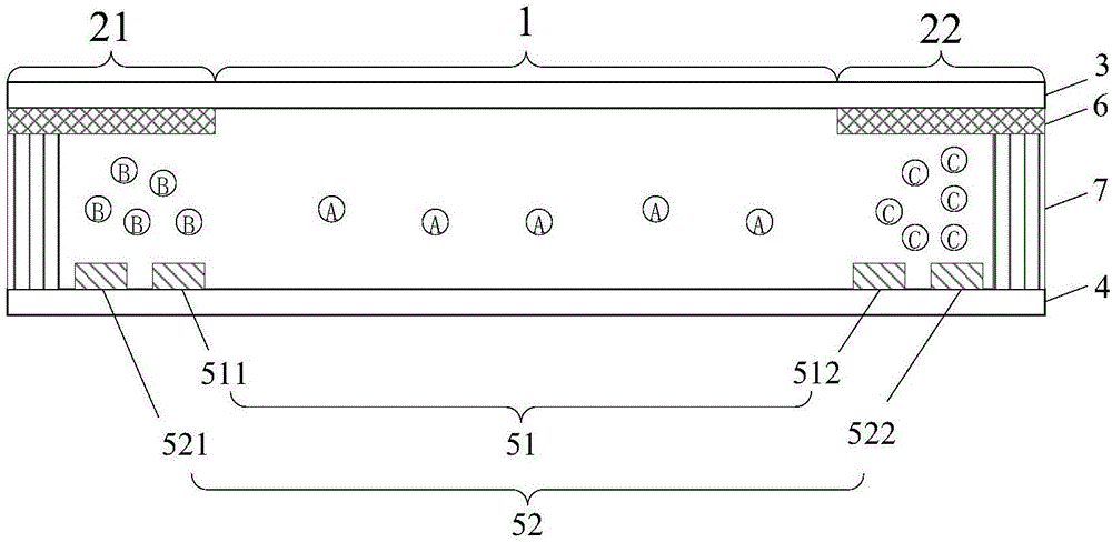
[0036] see figure 1 The color electronic paper provided by this embodiment includes: a display area 1 and a non-display area, and the color electronic paper provided by this embodiment further includes: a first substrate 3 and a second substrate 4 oppositely arranged; the first substrate 3 and the second substrate Charged particles of various colors are filled between the substrates 4 . A voltage control unit 5 is provided on the surface of the first substrate 3 opposite to the second substrate 4; or, a voltage control unit 5 is provided on the surface of the second substrate 4 opposite to the first substrate 3;

[0037] The voltage control unit 5 is used to control the charged particles of the target color to be located in the display area 1 and to control the charged particles of non-target colors to be located in the non-display area.

[0038] During specific implementation, after the target color is obtained, the charged particles of the target color are controlled by the...

Embodiment 2

[0058] This embodiment also provides a display device, including the color electronic paper provided in the above embodiment, the beneficial effect of which is the same as that of the above color electronic paper, and will not be repeated here.

Embodiment 3

[0060] This embodiment provides a color electronic paper display method, which is applied to the color electronic paper provided in the first embodiment, including: acquiring the target color, applying voltage to charged particles of various colors according to the target color, and controlling the charged particles of the target color Charged particles that are located in the display area and control the non-target color are located in the non-display area.

[0061] From the above display method of color electronic paper, it can be seen that in the display method of color electronic paper provided in this embodiment, the charged particles of the target color are controlled to be located in the display area, and the charged particles of non-target colors are controlled to be located in the non-display area, thus avoiding the Charged particles of non-target colors enter the display area, thereby eliminating the color shift problem caused by the layered arrangement of charged par...


PUM


Abstract

The invention discloses color electronic paper, a display device and a display method, and relates to the field of display technologies. By the aid of the color electronic paper, the display device and the display method, the problem of color errors due to layered arrangement of existing charged particles with different colors in display procedures can be solved. The color electronic paper comprises a first substrate and a second substrate. The first substrate and the second substrate are opposite to each other; spaces between the first substrate and the second substrate are filled with charged particles with various colors; a voltage control unit is arranged on the surface, which is opposite to the second substrate, of the first substrate or is arranged on the surface, which is opposite to the first substrate, of the second substrate; the charged particles with target colors can be positioned in a display region under the control of the voltage control unit, and the charged particle with non-target colors can be positioned in a non-display region under the control of the voltage control unit. The display device comprises the color electronic paper in the technical scheme. The display method is implemented by the aid of the color electronic paper in the technical scheme. The color electronic paper, the display device and the display method have the advantage that the color electronic paper is used for solving the problem of the color errors due to layered arrangement of the existing charged particles with the different colors in the display procedures.

Description

technical field [0001] The invention relates to the field of display technology, in particular to a color electronic paper and a display device. Background technique [0002] Color electronic paper is an ultra-thin and ultra-light display screen that is closer to natural paper. It has high resolution and large viewing angle, and is often used in electronic display devices. [0003] Currently, common color electronic paper includes an upper substrate, a lower substrate, an upper electrode disposed on the upper substrate, a lower electrode disposed on the lower substrate, and charged particles of various colors located between the upper and lower substrates. When the color electronic paper displays the color of charged particles with a higher threshold voltage, a voltage is applied to the upper electrode and the lower electrode so that the voltage difference between the upper electrode and the lower electrode meets the threshold voltage of the charged particles with a higher t...

Claims


Application Information

Patent Timeline
Patent Type & Authority Applications(China)
IPC IPC(8): G02F1/167G09G3/34
CPCG02F1/167G09G3/344
Inventor 颜莎宁刘庭良张俊瑞
Owner BOE TECH GRP CO LTD
Learn More