A device for measuring the pushover force of rod-shaped plant roots and its application method

A plant root and rod-shaped technology, which is used in measuring devices, test plants/trees, force/torque/work measuring instruments, etc., can solve the problems of lack of rod-shaped plant root lodging resistance measurement devices and large deviation of manual measurement results. , to achieve the effect of improving efficiency and accuracy, and a wide range of applications

Active Publication Date: 2019-05-10
NORTHEAST INST OF GEOGRAPHY & AGRIECOLOGY C A S
View PDF5 Cites 0 Cited by
  • Summary
  • Abstract
  • Description
  • Claims
  • Application Information

AI Technical Summary

Problems solved by technology

[0003] In order to solve the problem of lack of rod-shaped plant root lodging resistance measurement device in the prior art and the large deviation of manual measurement results, the present invention proposes a device for measuring rod-shaped plant root pushover force and its use method

Method used


Image

  • A device for measuring the pushover force of rod-shaped plant roots and its application method
  • A device for measuring the pushover force of rod-shaped plant roots and its application method
  • A device for measuring the pushover force of rod-shaped plant roots and its application method

Examples


specific Embodiment approach 1

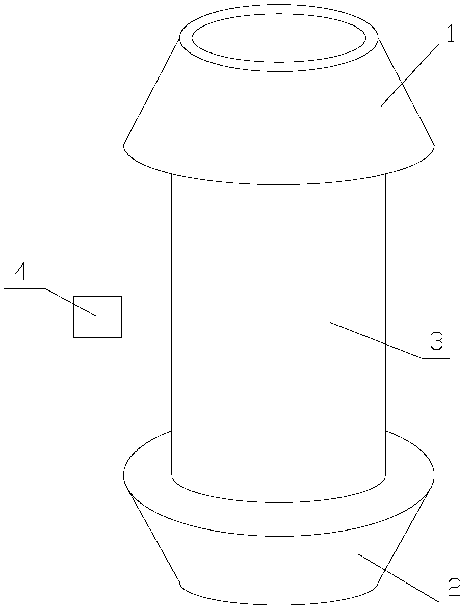
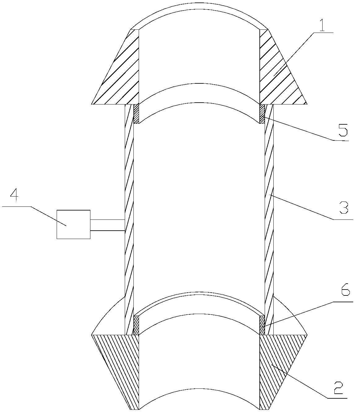
[0025] Specific embodiment one: the present embodiment is a kind of device that measures rod-shaped plant root pushing down force, and this device comprises upper soft device fixing sleeve 1, lower soft device fixing sleeve 2, middle hard connecting sleeve 3 and middle hard The dynamometer 4 connected vertically to the outer surface of the connecting sleeve 3;

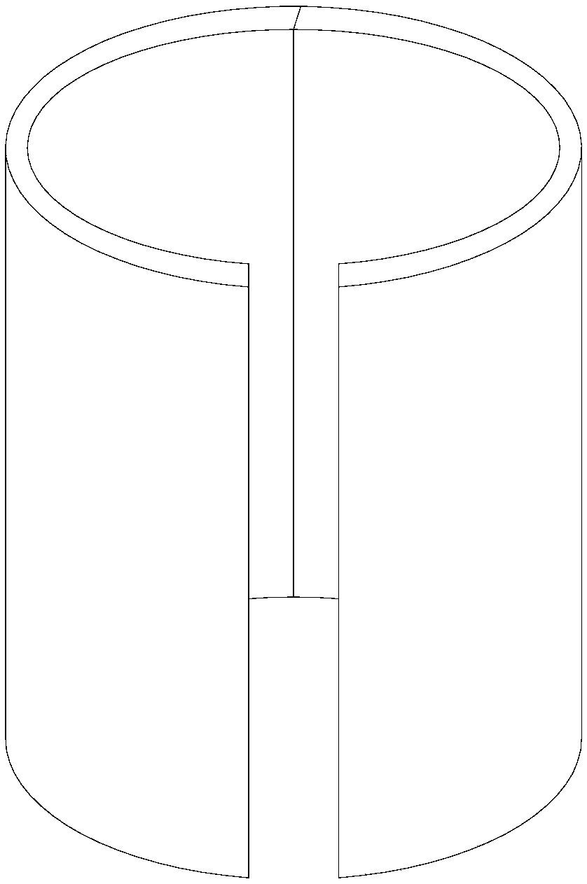
[0026] The fixed sleeve 1 of the upper soft device is in the shape of a truncated cone, the center of which is cylindrical and hollow, and the lower bottom surface of the truncated cone is provided with a first annular protrusion 5 coaxial with the fixed sleeve 1 of the upper soft device; The fixed sleeve 2 of the soft device is in the shape of a rounded truncated cone, the center of which is cylindrical and hollow, and the upper bottom surface of the rounded truncated shape is provided with a second annular protrusion 6 coaxial with the fixed sleeve 2 of the lower soft device; The connecting sleeve 3 is cylindrical, a...

specific Embodiment approach 2

[0031] Embodiment 2: This embodiment differs from Embodiment 1 in that: the material of the upper soft device fixing sleeve 1 is rubber; the material of the lower soft device fixing sleeve 2 is rubber. Other steps and parameters are the same as those in the first embodiment.

specific Embodiment approach 3

[0032] Embodiment 3: This embodiment differs from Embodiment 1 or Embodiment 2 in that: the dynamometer 4 is arranged in the middle of the outer surface of the middle hard connection sleeve 3 . Other steps and parameters are the same as those in Embodiment 1 or 2.


PUM

PropertyMeasurementUnit
diameteraaaaaaaaaa
heightaaaaaaaaaa

Abstract

The invention discloses a device for measuring the pull-down force of the root of a rod-shaped plant, and an application method of the device. The invention aims at solving problems that there is short of a root lodging resistance measurement device of the rod-shaped plant in the prior art and an error of a manual measurement result is big. The device comprises an upper soft device fixing sleeve, a lower soft device fixing sleeve, a central hard connection sleeve, and a force meter which is vertically connected with the external surface of the central hard connection sleeve. The application method comprises the steps: 1, keeping a plant stalk 30-130 cm higher than the ground surface, removing all other parts, and determining the setting height of the force meter; 2, carrying out the sleeving installation of the lower and upper soft device fixing sleeves and setting the central hard connection sleeve; 3, vertically connecting the force meter; 4, pushing the force meter, wherein the maximum fore displayed by the force meter serves as the pull-down force of the root of the rod-shaped plant. The device and method enable the success rate to be 98%, are suitable for the rod-shaped plants, and are accurate. The device and method are suitable for the measurement of the pull-down forces of the roots of the rod-shaped plants.

Description

Technical field: [0001] The invention relates to a device for measuring the push-down force of rod-shaped plant roots and its application method. Background technique: [0002] In order to measure the strength of root lodging resistance of rod-shaped plants, the method of artificially simulating root lodging is usually used. During operation, keep the middle and lower part of the plant, remove the parts other than the middle and lower part of the plant, and then push the plant stem with a dynamometer in a direction perpendicular to the plant stalk, and the plant stalk and the dynamometer are perpendicular to each other at 90°. °. During operation, the vertical state between the plant stem and the dynamometer should be maintained until the desired result of the test is obtained. But in actual operation, the tip of the dynamometer is attached to the surface of the stalk. Since the tip of the dynamometer is usually a flat surface and the stalk is cylindrical in shape, the co...

Claims


Application Information

Patent Timeline
Patent Type & Authority Patents(China)
IPC IPC(8): G01L5/00G01N33/00
CPCG01L5/00G01N33/0098
Inventor 刘胜群宋凤斌王洋齐晓宁朱先灿
Owner NORTHEAST INST OF GEOGRAPHY & AGRIECOLOGY C A S
Why Eureka
Try Eureka