Eureka AIR delivers breakthrough ideas for toughest innovation challenges, trusted by R&D personnel around the world.

Binary power generation system and binary power generation method

A power generation system, double-cycle technology, applied in the direction of machines/engines, steam engine devices, mechanical equipment, etc., can solve the problems of reduced efficiency, insufficient operating efficiency of the expander, etc., and achieve the effect of high-efficiency Rankine cycle

Inactive Publication Date: 2017-01-11
ANEST IWATA CORP
View PDF6 Cites 1 Cited by
  • Summary
  • Abstract
  • Description
  • Claims
  • Application Information

AI Technical Summary

Problems solved by technology

In addition, the pressure of the generated steam fluctuates greatly, so the operating efficiency of the expander may not be sufficient.
Therefore, in a Rankine cycle, the efficiency as a whole may decrease

Method used


Image

  • Binary power generation system and binary power generation method
  • Binary power generation system and binary power generation method

Examples


Embodiment Construction

[0016] Hereinafter, embodiments of the present invention will be described with reference to the drawings. In addition, in description of drawings, the same code|symbol is attached|subjected to the same element, and overlapping description is abbreviate|omitted.

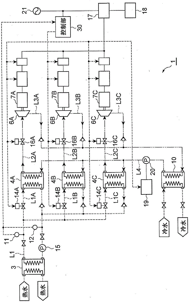
[0017] First, refer to figure 1 The two-cycle power generation system 1 of this embodiment will be described. figure 1 In , the solid line represents the electric circuit, and the dotted line represents the hot water circuit. The two-dot dash line indicates the circuit of the working medium. A dotted line connected to the control unit 30 represents a control loop.

[0018] Such as figure 1 As shown, the dual-cycle power generation system 1 is a power generation system that heats and evaporates a working medium with a relatively low boiling point using a relatively low temperature (for example, about 80-90° C.) heat source, and uses the steam to generate electricity. As the heat source, any heat source can be use...


PUM


Abstract

A binary power generation system (1) includes a plurality of evaporators (4A-4C), a condenser (10), a stop means (16A-16C), and a control unit (30). The evaporators (4A-4C) are connected to each of a plurality of displacement type expanders (6A-6C). The condenser (10) is connected to each of the displacement type expanders (6A-6C). The stop means (16A-16C) can stop circulation of an operating medium for each set of the evaporators (4A-4C) and the displacement type expanders (6A-6C) and circulation of a heat source medium for the evaporators (4A-4C). The control unit (30) controls the numbers of the evaporators (4A-4C) and the displacement type expanders (6A-6C) to be operated by controlling the stop means based on information on a heat amount of the heat source medium.

Description

technical field [0001] The present invention relates to a binary power generation system and a binary power generation method. Background technique [0002] As such a technique, a device described in Patent Document 1 (Japanese Patent Application Laid-Open No. 2008-175108 ) is known. The unit is a Rankine cycle power recovery unit with a single steam generator, multiple volumetric expanders and a condenser. The steam path of the steam generated by the steam generator is branched and connected to each expander. The condensed water supplied to the steam generator is heated and evaporated in the steam generator by the heat of the exhaust gas of the internal combustion engine, and is supplied to the expander. The vapor expanded by each expander is collected in one vapor passage, cooled and condensed in the condenser. Expansion of the steam in each expander rotates the power take-off shaft, and generates electricity by the induction generator. [0003] In this device, the num...

Claims


Application Information

Patent Timeline
Patent Type & Authority Applications(China)
IPC IPC(8): F01K7/02F01K11/02F01D15/10
CPCF01D15/10F01K7/02F01K11/02F01K23/02F01K25/10
Inventor 藤冈完宇波厚和泉孝明
Owner ANEST IWATA CORP
Why Eureka
Eureka Blog
Learn More