
Prestressed rock bolt foundation with replaceable bolts

A rock bolt and prestressing technology, which is applied in the direction of basic structure engineering and construction, can solve the problems of smaller diameter, increased cost, and uneven stress of the bottom flange, so as to improve economic value, save maintenance costs, and replace construction easy effect

Active Publication Date: 2018-08-24
BEIJING JANDC GEOTECHNICAL CONSTR LTD +1
View PDF10 Cites 0 Cited by
  • Summary
  • Abstract
  • Description
  • Claims
  • Application Information

AI Technical Summary

Problems solved by technology

First of all, the nut box and the nut are set separately. In order to realize the circumferential fixation of the nut, the nut needs to be welded on the lower anchor plate. cost; secondly, in order to meet the construction conditions, the plastic sleeve 42 and the anchor bolt 4 need a certain gap, and the entire anchor bolt 4 device is basically filled in the middle of the concrete, and the concrete is bound to produce plastic sleeve 42 in the process of pouring. The force of extrusion forces the deformation of the plastic sleeve 42 so that the anchor bolt 4 and the plastic sleeve 42 are not coaxial, and it is difficult to unscrew the broken anchor bolt 4 for replacement; again, the two ends of the plastic sleeve 42 are heated by shrinking The sleeve 41 is shrink-sealed, so that the caliber at the insertion port of the plastic sleeve 42 becomes smaller, see Figure 14 As shown, then the new anchor bolt 4 is difficult to insert in the plastic sleeve 42, thereby causing the replacement anchor bolt 4 to be inconvenient

Method used


Image

  • Prestressed rock bolt foundation with replaceable bolts
  • Prestressed rock bolt foundation with replaceable bolts
  • Prestressed rock bolt foundation with replaceable bolts

Examples


Embodiment 1

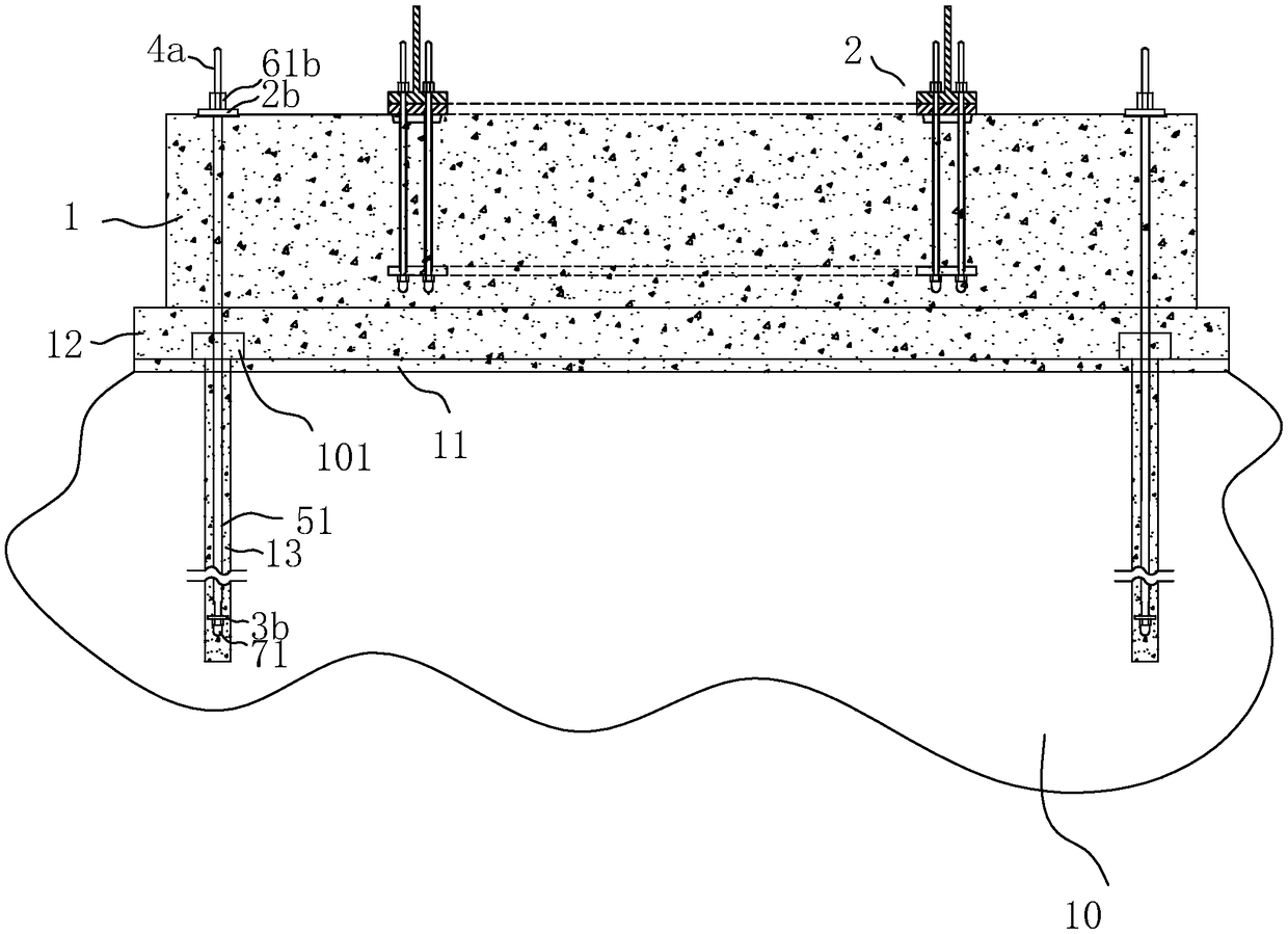
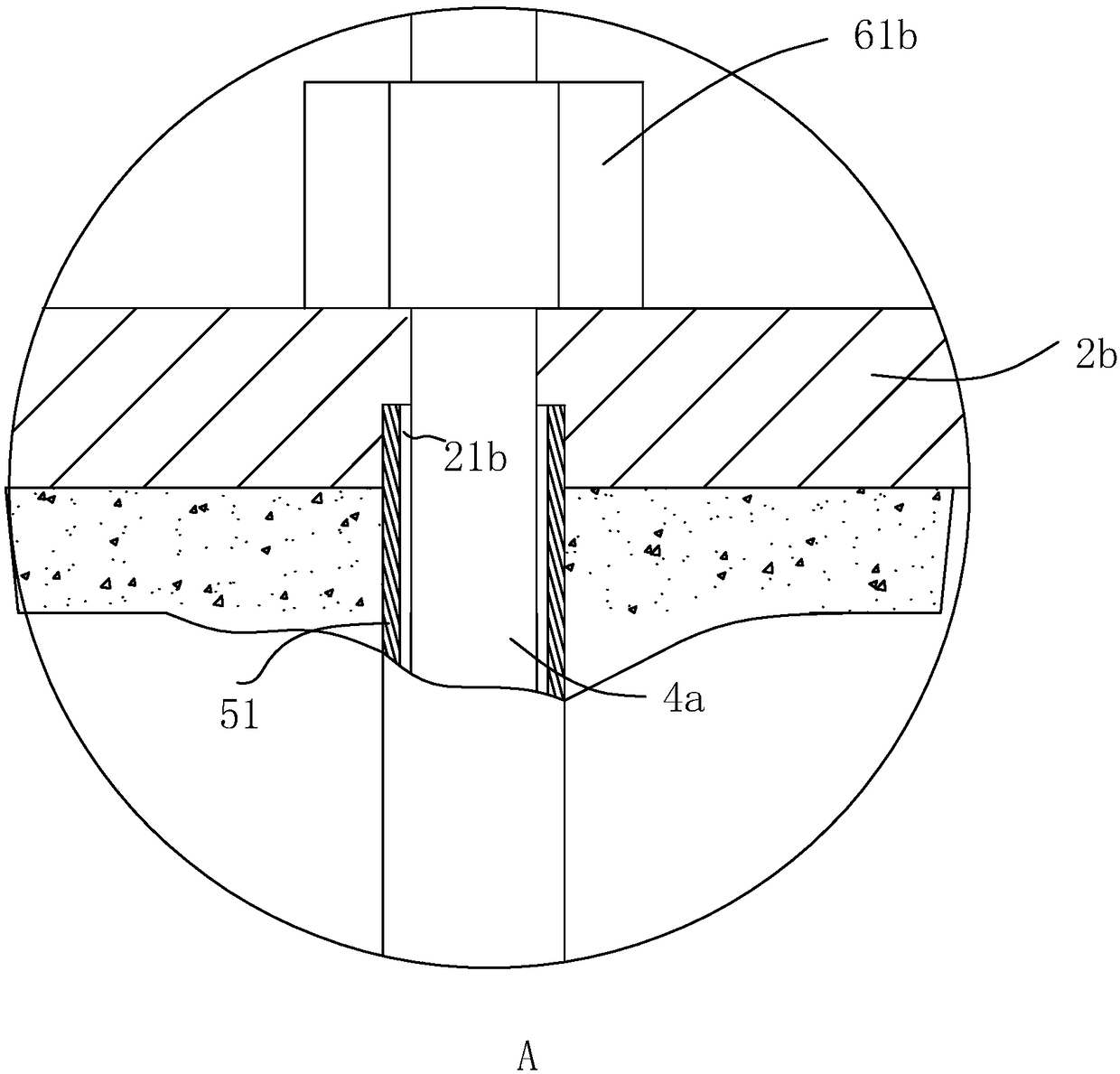
[0052] Embodiment 1, see Figures 1 to 2 As shown, a prestressed rock bolt foundation with replaceable bolts includes a poured concrete leveling layer 11 poured on the rock mass 10, a concrete cushion 12, and a cylindrical concrete cap 1 and embedded in the concrete cap 1 Anchor cage ring assembly 2 in the middle, prestressed rock bolts 4a are distributed around the concrete cap 1, and prestressed rock bolts 4a pass through the top bolt fixing plate 2b, concrete cap 1, concrete cushion 12, polyethylene The benzene plate 101 and the concrete leveling layer 11 are inserted into the prestressed rock bolt hole of the rock mass 10 .

[0053] The outer casing of the prestressed rock bolt 4a is provided with a concrete rigid casing 1 51 for isolation, and the two ends of the rigid casing 51 are sealed and connected.

[0054] The upper end of the prestressed rock bolt 4a is connected to the top bolt fixing plate 2b through the top nut 61b, and the lower end of the prestressed rock bo...

Embodiment 2

[0062] Embodiment 2, see Figure 9 and Figure 10 , a prestressed rock bolt foundation with replaceable bolts. Compared with Embodiment 2, the difference is that the prestressed rock bolt 4a is divided into two parts: the first prestressed rock bolt 41a, the second prestressed rock bolt Rod 42a, connecting sleeve 43, the first prestressed rock bolt 41a and the second prestressed rock bolt 42a are provided with mounting holes 431 on the end face of the connecting sleeve 43, and the rigid sleeve 51 is sleeved on the first prestressed rock bolt On 41a, the lower end of the first rigid sleeve 51 extends into the installation hole 431 , and the diameter of the installation hole 431 is equal to the diameter of the first rigid sleeve 51 .

[0063] In this embodiment, the top end of the first prestressed rock bolt 41a is set in a flat shape, so that it can be taken out with a wrench.

Embodiment 4

[0064] Embodiment 4, see Figure 11 As shown, a prestressed rock bolt foundation with replaceable bolts differs from Embodiment 1 in that in the anchor cage ring assembly 2, the anchor bolt 4b is a double-single structure.


PUM


Abstract

The invention discloses a prestress rock anchor rod foundation with anchor rods capable of being replaced. The prestress rock anchor rod foundation comprises a concrete bearing platform formed by concrete. A plurality of high-strength grouting piles circumferentially distributed are arranged on the bottom face of the concrete bearing platform. The prestress rock anchor rods are coaxially arranged in the high-strength grouting piles. The upper ends of the prestress rock anchor rods are connected with top anchor rod fixing plates through top nuts. An anchor cage ring assembly is arranged in the center of the concrete bearing platform. The prestress rock anchor rods are sleeved with first rigidity sleeves used for isolating grouting materials. The lower ends of the prestress rock anchor rods penetrate bottom anchor rod fixing plates and are in threaded connection with first isolation caps integrally arranged and used for isolating concrete. The opening ends of the first isolation caps are in sealed connection with the bottom anchor rod fixing plates. The integrally-arranged isolation caps are adopted in the prestress rock anchor rod foundation, a structure form of a sealing assembly is changed, and the prestress rock anchor rod foundation has the beneficial effects that cost is reduced, and replacing is convenient.

Description

technical field [0001] The invention relates to the technical field of civil engineering in the wind power generation industry, in particular to a prestressed rock bolt foundation with replaceable bolts and a replacement construction method. Background technique [0002] At present, the racks and towers of large or very large equipment, including wind generators, wind turbines, power line street lighting and signaling devices, bridge supports, commercial signs, highway signboards, ski lifts and other buildings are all constructed on site. Concrete foundation support. [0003] Especially in recent years, with the rapid development of my country's economy and the improvement of social environmental protection awareness, the scale of wind power generation is increasing day by day, and wind turbine towers have gradually become the mainstream. In order to adapt to different geological conditions, there will be different concrete foundations. In mountainous conditions, such as ha...

Claims


Application Information

Patent Timeline
Patent Type & Authority Patents(China)
IPC IPC(8): E02D27/44E02D27/42
CPCE02D27/42E02D27/425E02D27/44
Inventor 石健申宽育胡永柱李振作田伟辉崔振磊瓮文芳张钦喜张俊杰马云龙石岩季东波
Owner BEIJING JANDC GEOTECHNICAL CONSTR LTD
Learn More