
Metal workpiece diversion turning device

A technology of turning devices and metal workpieces, which is applied in metal processing and other directions, can solve problems such as bearing congestion, sorting speed cannot keep up with grinding bearings in time, time-consuming and labor-intensive problems, and achieve the effect of preventing bearing congestion

Inactive Publication Date: 2017-01-11
JIANGSU HAILONG ELECTRICAL APPLIANCE
View PDF0 Cites 0 Cited by
  • Summary
  • Abstract
  • Description
  • Claims
  • Application Information

AI Technical Summary

Problems solved by technology

If the bearings after deburring are manually sorted, it will not only take time and effort, but also the sorting speed cannot keep up with the speed of grinding the bearings in time, which will easily cause bearing congestion

Method used


Image

  • Metal workpiece diversion turning device

Examples


Embodiment Construction

[0009] The technical solution will be described in detail below through a best embodiment, but the protection scope of the present invention is not limited to the embodiment.

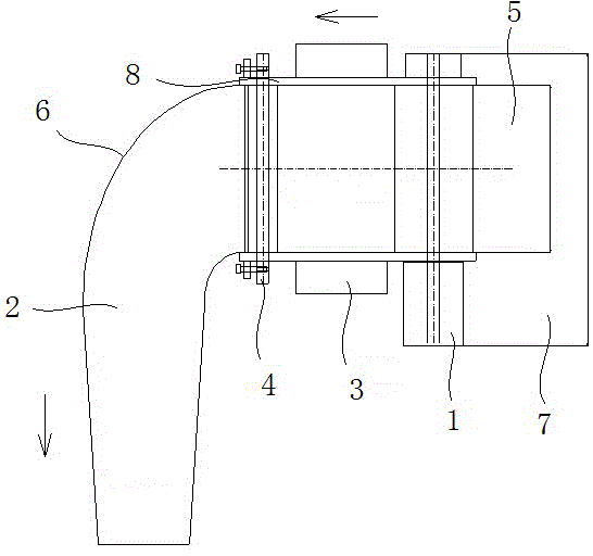
[0010] Such as figure 1 As shown, the diversion and turning device for metal workpieces includes a first conveyor belt 5, a second conveyor belt 2 and a conveyor platform 7, and the first conveyor belt 5 and the second conveyor belt 2 are perpendicular to each other. A deceleration motor is set on the conveying platform 7, and the decelerating motor 1 is connected with a roller, and the roller is arranged under the first conveying crawler belt 5, and the roller is in contact with the lower surface of the first conveying crawler belt 5, and the first conveying crawler belt 5 is in contact with the first conveying crawler belt 5. The crawler belt 5 is connected with the second conveying crawler belt 2 through an arc segment 6 .

[0011] A driven gear 3 is also provided under the first conveying crawler b...


PUM


Abstract

The invention discloses a metal workpiece diversion turning device which comprises a first conveying crawler belt, a second conveying crawler belt and a conveying platform, wherein the first conveying crawler belt and the second conveying crawler belt are perpendicular to each other; a gear motor is arranged on the conveying platform, and is connected with a roller; the roller is arranged under the first conveying crawler belt, and is in contact with the lower surface of the first conveying crawler belt; the first conveying crawler belt and the second conveying crawler belt are connected with each other via an arc section; and baffles are arranged on two sides of the arc first conveying crawler belt, and are fastened with each other via a long bolt. As a diversion turning device body is arranged between the first conveying crawler belt and the second conveying crawler belt, timely running of a bearing after deburring can be realized to avoid on-site jamming of bearings.

Description

technical field [0001] The invention relates to the technical field of removing burrs on the surface of metal workpieces in mechanical processing, and more specifically relates to a diversion turning device for metal workpieces. Background technique [0002] After the bearing is deburred by the deburring machine, it needs to be run in time to cooperate with the bearing that is automatically sent to the deburring machine for deburring. If the bearings after deburring are manually sorted, it will not only take time and effort, but also the sorting speed cannot keep up with the speed of grinding the bearings in time, which will easily cause bearing congestion. If the conveying track is used to directly transport and drop into the container, it is necessary to extend the conveying track, which requires higher space requirements on the production site. Therefore, turning diversion operation is required to save space on the production site. Contents of the invention [0003] P...

Claims


Application Information

Patent Timeline
IPC IPC(8): B23Q7/00
CPCB23Q7/00
Inventor 朱圣明李杰
Owner JIANGSU HAILONG ELECTRICAL APPLIANCE
Learn More