
Feeding device for tableware polishing

A tableware and blade technology, which is applied in the field of feeding devices for tableware polishing, can solve problems such as poor operating environment, operator frostbite, and potential safety hazards, and achieve high work efficiency, compensation for processing errors, and low labor intensity.

Pending Publication Date: 2019-03-22
TIANJIN SHIDAI CHUANGYE TECH CO LTD
View PDF0 Cites 0 Cited by
  • Summary
  • Abstract
  • Description
  • Claims
  • Application Information

AI Technical Summary

Problems solved by technology

[0002] In the process of forming tableware, it needs to go through various processes such as forming, forging, grinding and polishing. In the process of polishing, because the grinding wheel is used for grinding to ensure that the outer surface of the tableware is smooth. In the process of grinding the vertical side of the parameter, it is necessary to realize automatic material pushing, but before pushing the material, it is necessary to manually place the tableware into the automatic material pushing device, and the tableware is set between the automatic material pushing device and the grinding wheel. The process requires manual operation. During the feeding process, the operator has a downward movement, and the tableware is stuck in the automatic material pushing device. This downward movement often touches the grinding wheel during the operation. There are certain safety hazards, and when the grinding wheel is running at high speed, it is necessary to spray liquid to cool down and improve the accuracy of grinding, especially in winter, when the temperature of the liquid is low, it is often wetted by the spray liquid when manually installing the tableware. Sustained low temperature will cause frostbite to the operator, poor operating environment

Method used


Image

  • Feeding device for tableware polishing
  • Feeding device for tableware polishing
  • Feeding device for tableware polishing

Examples


Embodiment Construction

[0024] It should be noted that the embodiments of the present invention and the features in the embodiments can be combined with each other if there is no conflict.

[0025] In the description of the present invention, it should be understood that the terms "center", "longitudinal", "transverse", "upper", "lower", "front", "rear", "left", "right", " The orientation or positional relationship indicated by "vertical", "horizontal", "top", "bottom", "inner", "outer" etc. is based on the orientation or positional relationship shown in the drawings, and is only for the convenience of describing the present invention and The description is simplified, rather than indicating or implying that the pointed device or element must have a specific orientation, be constructed and operated in a specific orientation, and therefore cannot be understood as a limitation of the present invention. In addition, the terms "first", "second", etc. are only used for descriptive purposes, and cannot be und...


PUM


Abstract

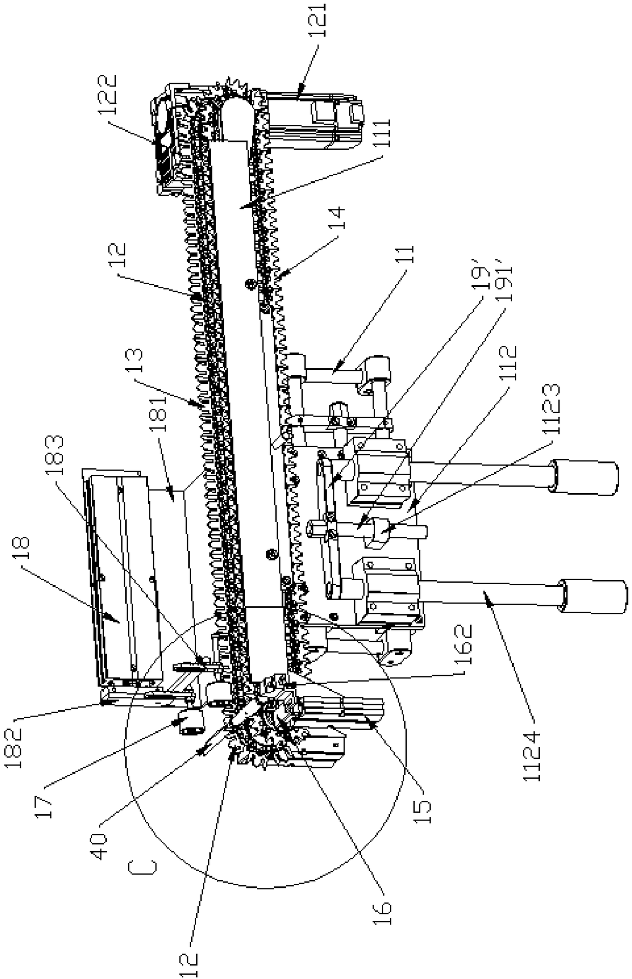
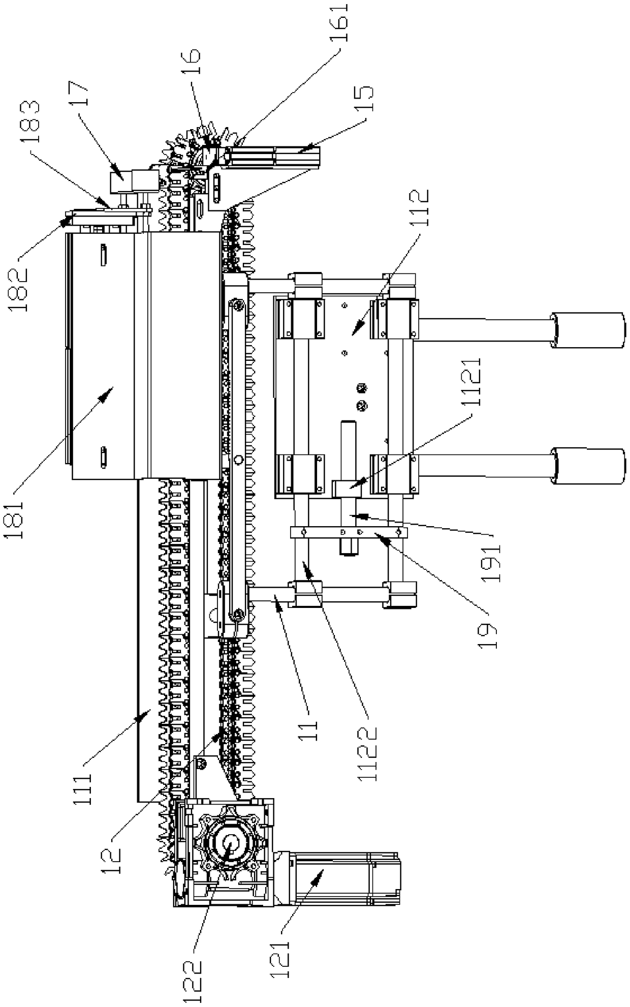
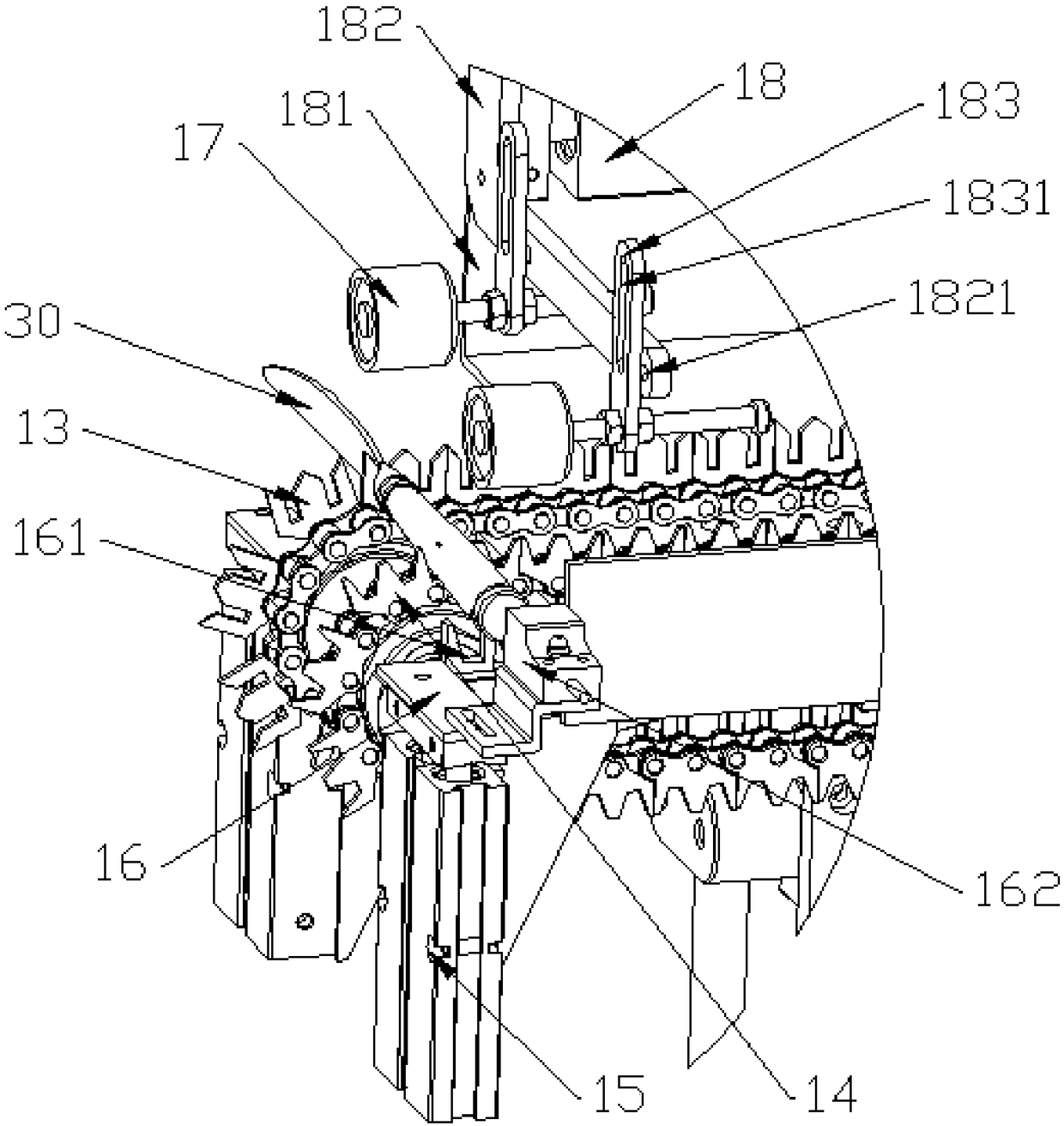
The invention provides a feeding device for tableware polishing, and belongs to the field of automatic feeding equipment. The feeding device comprises a fixing frame which is provided with two rows ofconveying chains arranged in parallel; a front frame blade is arranged on one sides of the conveying chains, and a rear frame blade is arranged on the other sides of the conveying chains; the front frame blade and the rear frame blade are oppositely arranged to position the same tableware; lifting cylinders are arranged on the two sides of one ends of the conveying chains; brackets are fixedly arranged on force output shafts of the lifting cylinders; positioning grooves are formed in the brackets; electromagnets are arranged above the conveying chains and correspond to the side face of the tableware; and the electromagnets and a force output shaft of a pushing cylinder are arranged in a fixedly locked mode, and the force output shaft of the pushing cylinder is arranged parallel to the longitudinal centerlines of the conveying chains. A plurality tools can be automatically and continuously fed, the efficiency is high, an operator gets away from a grinding wheel during operation, and the safety is high.

Description

Technical field [0001] The invention belongs to the field of automatic feeding equipment and relates to a feeding device for tableware polishing. Background technique [0002] In the process of forming tableware, it needs to go through various processes such as forming, forging, grinding and polishing. During the polishing process, because the grinding wheel is used for grinding, the outer surface of the tableware is smooth. The current production process is correct. In the process of polishing the vertical side of the parameters, it needs to be able to realize automatic pushing, but the tableware needs to be manually placed in the automatic pushing equipment before pushing. The tableware is set between the automatic pushing equipment and the grinding wheel. The process requires manual operation. During the loading process, the operator has an oblique downward movement, and the tableware is stuck in the automatic pushing equipment. This oblique downward movement will often hit th...

Claims


Application Information

Patent Timeline
Patent Type & Authority Applications(China)
IPC IPC(8): B24B41/00
CPCB24B41/005
Inventor 田增慧
Owner TIANJIN SHIDAI CHUANGYE TECH CO LTD
Learn More