
A sheet clamping device for laser cutting equipment

A clamping device and laser cutting technology, used in laser welding equipment, welding/cutting auxiliary equipment, auxiliary devices, etc., can solve the problems of inconvenient manual cleaning of waste, troublesome installation and disassembly, and high laser cutting temperature, and achieve convenient cleaning. Recycling waste, easy operation, good stability

Inactive Publication Date: 2018-05-04
重庆聚纵贸易有限公司
View PDF9 Cites 0 Cited by
  • Summary
  • Abstract
  • Description
  • Claims
  • Application Information

AI Technical Summary

Problems solved by technology

[0004] For this reason, the technical problem to be solved by the present invention is that the installation and disassembly of the sheet material clamping device used for laser cutting equipment in the prior art is relatively troublesome, and the position of the clamping part is fixed, so it can only be used for plates of fixed size. The material is clamped, the scope of application is small, the laser cutting temperature is high, and it is inconvenient to manually clean up the waste, so a sheet clamping device for laser cutting equipment is proposed

Method used


Image

  • A sheet clamping device for laser cutting equipment
  • A sheet clamping device for laser cutting equipment
  • A sheet clamping device for laser cutting equipment

Examples


Embodiment Construction

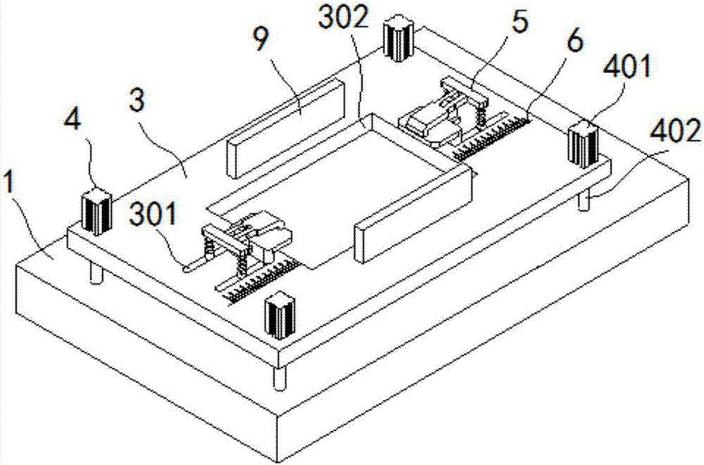
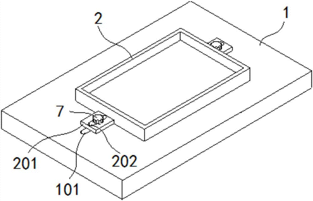
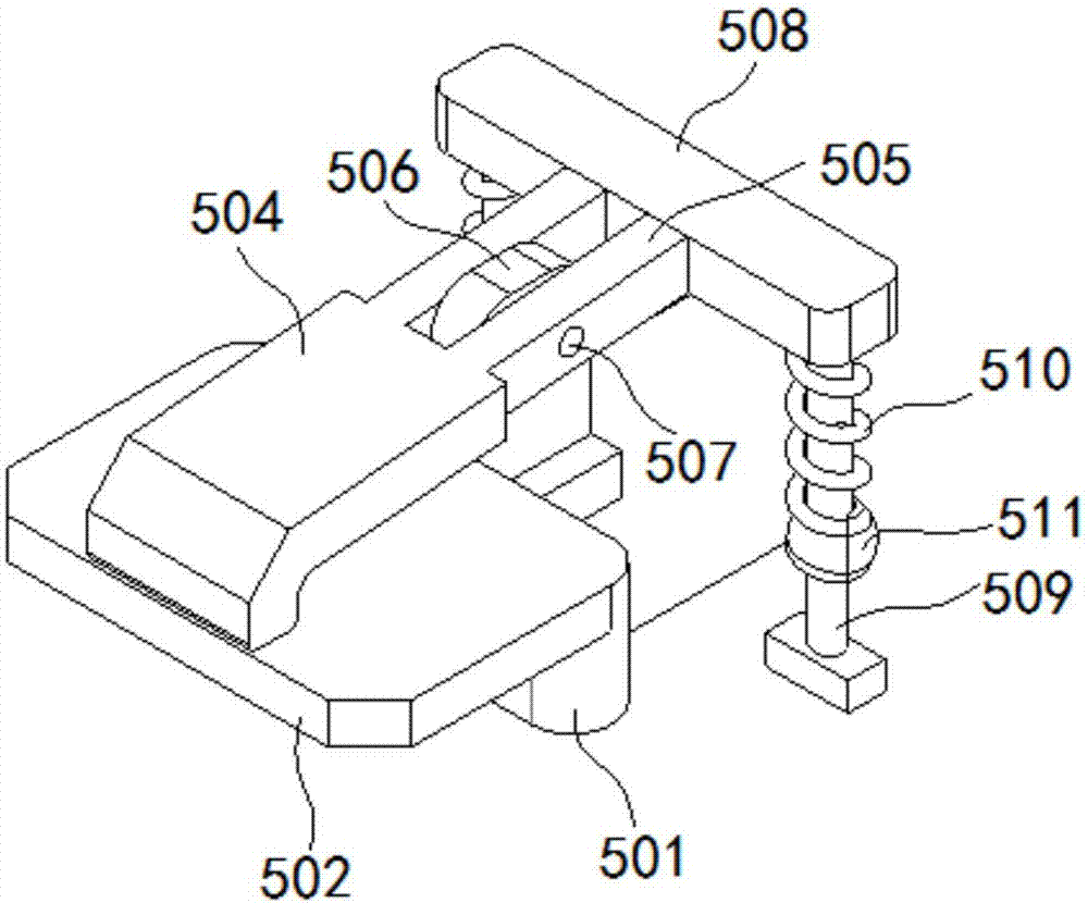
[0027] Such as figure 1 , figure 2 As shown, the sheet material clamping device for laser cutting equipment of the present invention includes:

[0028] The bottom plate 1 has a first mounting groove 101 formed on the bottom plate 1.

[0029] Discharge box 2, the discharge box 2 is arranged above the bottom plate 1, the lower end of the side of the discharge box 2 is formed with a mounting plate 201, the mounting plate 201 is formed with a second mounting groove 202, so The second installation groove 202 and the first installation groove 101 are arranged correspondingly.

[0030] The processing plate 3 and the lifting cylinder 4 are arranged above the bottom plate 1, the lifting cylinder 4 is provided between the processing plate 3 and the bottom plate 1, and a number of guides are provided on the processing plate 3 槽301. A rectangular processing hole 302 is formed at the center of the processing plate 3, and the length and width of the upper port of the discharge box 2 are larger t...


PUM


Abstract

The invention discloses a plate clamping device for laser cutting equipment. The device comprises a bottom plate, a discharging box, a processing plate, lifting cylinders, clamping seats and baffles. By means of the clamping seats arranged on the processing plate, a plate can be conveniently mounted and dismounted, the clamping is reliable, and the stability is high; besides, the clamping seats can be moved according to the size of the plate, therefore, the application range is broad. By the arrangement of the discharging box which is equipped with a mounting plate and is detachably arranged on the bottom plate, waste can be cleaned and recycled conveniently. The device is simple in structure, convenient to operate, high in reliability and good in stability.

Description

Technical field: [0001] The invention belongs to the technical field of laser cutting equipment, and in particular relates to a sheet material clamping device for laser cutting equipment. Background technique: [0002] Laser cutting is to irradiate the material with a high-power density laser beam to quickly heat the material to vaporization temperature and evaporate to form holes. As the beam moves on the material, the holes continuously form slits with a narrow width (such as about 0.1mm). Cutting of materials. Laser cutting is one of the thermal cutting methods. Laser cutting can be divided into four categories: laser vaporization cutting, laser melting cutting, laser oxygen cutting and laser scribing and controlled fracture. It has the advantages of good cutting quality, high cutting efficiency, fast cutting speed, etc. It is a commonly used thermal cutting method for some sheet materials. [0003] In the prior art, the clamping and positioning of the sheet material during l...

Claims


Application Information

Patent Timeline
Patent Type & Authority Patents(China)
IPC IPC(8): B23K26/70B23K37/04
CPCB23K26/702B23K37/0443
Inventor 叶芳
Owner 重庆聚纵贸易有限公司
Learn More