
Laser automatic welding control method of power battery pack

A power battery pack and automatic welding technology, applied in laser welding equipment, welding equipment, manufacturing tools, etc., can solve the problems of strict technical maintenance requirements, low work efficiency, complex structure, etc., and achieve good environmental compatibility and convenient maintenance and modification , a wide range of effects

Inactive Publication Date: 2017-01-11
武汉市楚源光电有限公司
View PDF5 Cites 2 Cited by
  • Summary
  • Abstract
  • Description
  • Claims
  • Application Information

AI Technical Summary

Problems solved by technology

[0005] 1. The traditional single-product soft-pack lithium battery pack laser automatic welding production line adopts high-performance PLC for overall control. Although the tooling is simple and can well meet the requirements of various processes, continuity, and data entry and analysis, it can only Satisfied with the welding process of a single type of battery pack, if the model is switched, it will have a relatively large impact on the commissioning of the laser welding production line, and because the commissioning time will affect production, the complex structure, expensive price, and strict technical maintenance requirements make this This kind of automatic welding production line brings too much burden to general welding users, so it cannot be well used in application processing and actual production;
[0006] 2. Manual loading board single-machine welding Since the welding trajectory can be input through the DXF file, switching the battery model is relatively simple, but the stability is too poor, and the overall process has many links, making its work efficiency extremely low, and it is impossible to mass-produce Welding production cannot be carried out continuously, and other functions of the battery pack cannot be continuously tested, installed and measured, so the success rate of welding cannot be guaranteed at all, and the data analysis and input of the battery pack during the entire process cannot be performed. extremely harsh

Method used


Image

  • Laser automatic welding control method of power battery pack

Examples


Embodiment Construction

[0027] The technical solutions in the embodiments of the present invention will be clearly and completely described below in conjunction with the accompanying drawings in the embodiments of the present invention. Obviously, the described embodiments are only part of the embodiments of the present invention, not all of them. Based on the implementation manners in the present invention, all other implementation manners obtained by persons of ordinary skill in the art without making creative efforts belong to the scope of protection of the present invention.

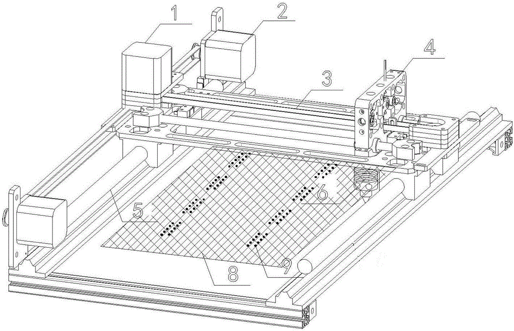
[0028] refer to figure 1 , the power battery pack laser automatic welding control method of the present invention can adopt existing laser welding equipment, which includes a Y-axis servo motor 1, an X-axis servo motor 2, a Y-axis servo module 3, a relay 4 for performing light output, and an X-axis servo motor. Axis servo module 5 and laser 6, wherein, the X-axis servo module 5 drives the laser 6 to move along the X-axis di...


PUM


Abstract

The invention provides a laser automatic welding control method of a power battery pack. Full-automatic welding can be achieved through simple parameter inputting, alternate operation can be performed by using a double-laser welding device, the working efficiency is greatly improved, and when the model of the power battery pack is needed to be switched, the power battery pack model is modified on a PLC control touch screen only through mechanical adjustment, the operation is simple, and the maintenance and modification are convenient. The compatibility of product is good, one production line can be used for laser welding of most of soft-packaged battery packs on the market, and the performance cost ratio is high. The welding precision is good in controllability, a usage environment is good in compatibility, and an application range is wide.

Description

technical field [0001] The invention relates to the technical field of automatic control, in particular to a laser automatic welding control method for a power battery pack. Background technique [0002] At present, the welding process of soft-packed lithium battery packs by laser welding is very common. Basically, the nickel strips of the two tabs of each soft-packed battery are laser-welded with the nickel-plated copper substrate, and according to different polarities Welding of metallic materials with different properties. At present, the national standard does not have strict regulations on the shape and size of lithium batteries. Therefore, as the application of lithium batteries becomes more and more widespread, the specifications and types of soft-pack lithium batteries of various manufacturers are different, and the number of welding points is different. Especially laser If the automatic welding production line only welds one or two types of pouch battery packs, the...

Claims


Application Information

Patent Timeline
Patent Type & Authority Applications(China)
IPC IPC(8): B23K26/21
CPCB23K26/21
Inventor 闻靖
Owner 武汉市楚源光电有限公司
Learn More