Smart home illuminating system control method

A smart home and lighting system technology, applied in the field of lighting systems, can solve the problems of being unable to distinguish between day and night, unable to realize remote control, and unable to know the state of home lighting in time

Inactive Publication Date: 2017-01-04
张颖
View PDF2 Cites 4 Cited by
  • Summary
  • Abstract
  • Description
  • Claims
  • Application Information

AI Technical Summary

Problems solved by technology

[0003] In the existing technology, users cannot keep abreast of all the lighting conditions inside the home outside the home environment. In order to keep abreast of the lighting conditions inside the home and maintain the normal operation of the home, solid and reliable technical support is required
The disadvantages of the existing technology are: 1) There is no perception of the intensity of the ambient light, and it is difficult to distinguish between day and night, and the light can only be controlled by human actions; 2) It can only realize wireless control in the local area network, but cannot remote control

Method used


Image

  • Smart home illuminating system control method
  • Smart home illuminating system control method

Examples


Embodiment Construction

[0015] The present invention will be further described in detail below in conjunction with the accompanying drawings, so that those skilled in the art can implement it with reference to the description.

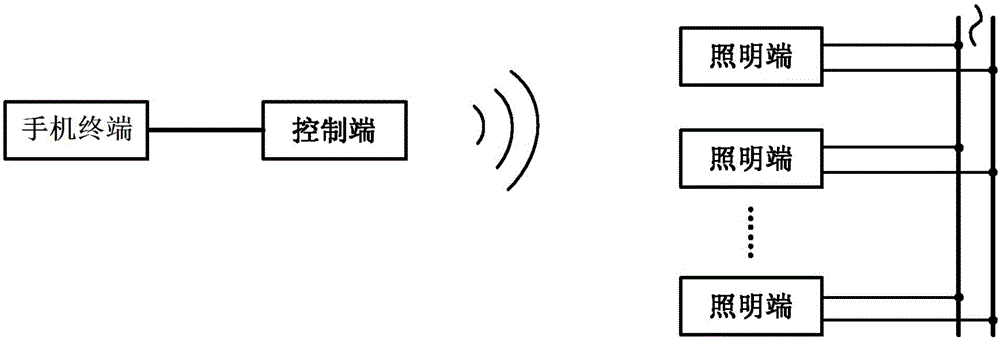
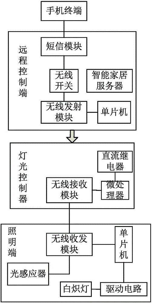
[0016] The control method of the smart home lighting system is characterized in that the method includes: the control terminal is connected to the mobile terminal, and the mobile terminal will find that there is at least one lighting terminal and a lighting controller. If the acquired lighting controller device does not display The current state of the light, the mobile terminal will issue a query command; the query command is received and processed by the control terminal, and converted into a message format between the control terminal and the lighting terminal, and transmitted through the wireless module; The brightness value of the current lamp is obtained from the controller, and then the response message is sent out through the wireless module of the lighting controller....


PUM


Abstract

The present invention is that a controlling end is connected to a mobile phone terminal, the mobile phone terminal may discover at least one illuminating end and a lighting controller, if an obtained lighting controller device does not display a current state of a light, the mobile phone terminal sends a query command; the query command is received and processed by the controlling end, and is transmitted by a wireless module; after receiving the query command, the illuminating end obtains a brightness value of the current light from an optical inductor, and then transmits a response message by using a wireless module of the lighting controller, wherein the response message is obtained by the controlling end, and is forwarded to the mobile phone terminal; when it is required to change a working state of the light, the mobile phone terminal sends a command, and the command is received by a remote controlling end and is forwarded after processing, to separately or simultaneously control any quantity of illuminating ends, thereby achieving an objective of controlling illuminating end brightness; and if a host side sends a light brightness control command, the illuminating end reads a value of the optical inductor after adjusting the brightness, and feeds back the value to the controlling end, and the value is finally learned by the mobile phone terminal.

Description

technical field [0001] The invention relates to a lighting system, in particular to a control method for a smart home lighting system. Background technique [0002] Smart home technology uses advanced computers, embedded systems and network communication technologies to connect various devices in the home (such as lighting systems, environmental control, security systems, and network appliances) through a home network. With the continuous improvement of people's living standards, home life has also entered a new stage of development. Lighting, refrigerators, rice cookers, air conditioners, washing machines, computers, microwave ovens, piped gas, and tap water have become indispensable in modern family life. At the same time, with the rapid economic development, people have higher and higher requirements for the comfort of family life, especially in the convenience of home appliances. Home gateways can be used to control home appliances such as lights and air conditioners, s...

Claims


Application Information

Patent Timeline
Patent Type & Authority Applications(China)
IPC IPC(8): H05B37/02
CPCH05B47/105H05B47/19Y02B20/40
Inventor 张颖
Owner 张颖
Why Eureka
Try Eureka