
Distributed antenna system and signal transmitting method

A distributed antenna and antenna technology, applied in the field of communication, can solve the problems of difficult construction and high cost

Inactive Publication Date: 2017-01-04
HUAWEI TECH CO LTD
View PDF4 Cites 3 Cited by
  • Summary
  • Abstract
  • Description
  • Claims
  • Application Information

AI Technical Summary

Problems solved by technology

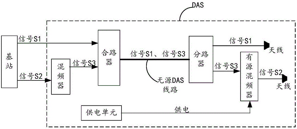
[0006] In order to solve the above problems, the present invention innovates the transmission architecture of the existing DAS, and proposes a distributed antenna system and a signal transmission method, so as to solve the problems caused by the existing implementation of power supply to the active mixer at the remote end of the DAS. Difficult construction and high cost

Method used


Image

  • Distributed antenna system and signal transmitting method
  • Distributed antenna system and signal transmitting method
  • Distributed antenna system and signal transmitting method

Examples


Embodiment 1

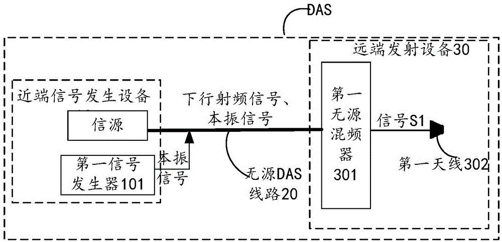
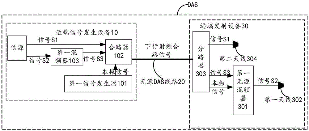
[0140] figure 2 A structural diagram of a Distributed Antenna System (DAS for short) provided for an embodiment of the present invention, as shown in figure 2As shown, the DAS may include: a near-end signal generating device 10, a passive DAS line 20, and a far-end transmitting device 30; 30 is located at the output port of the passive DAS line 20; it should be noted that the input port and the output port described in the embodiment of the present invention are determined relative to the transmission direction of the downlink radio frequency signal, and do not limit the specific location of the device .

[0141] The near-end signal generating device 10 is used to generate signals and is located in the computer room, and may include: any device that generates signals, and devices that perform mixing, combining, and other processing on the generated signals, and may include a source, a first signal Generator 101; where, the signal source may refer to any device that generat...

Embodiment 2

[0213] Figure 8 A signal transmission method provided by the embodiment of the present invention is executed by the DAS described in Embodiment 1, the near-end signal generating device, the passive DAS line and the remote transmitting device, characterized in that the near-end signal generating device Including: a signal source, a first signal generator; the remote transmitting device includes: a first passive mixer and a first antenna; as Figure 8 As shown, the method may include:

[0214] Step 101: the first signal generator generates a first local oscillator signal, and sends the first local oscillator signal to the first passive mixer through the passive DAS line.

[0215] Step 102: The first passive mixer receives the first local oscillator signal and the downlink radio frequency signal with the second radio frequency band.

[0216] Wherein, the downlink radio frequency signal of the second radio frequency band is: a signal generated by mixing the first local oscillat...

Embodiment 3

[0284] Figure 10 It shows a structural diagram of a distributed antenna system DAS provided by an embodiment of the present invention, which is used to implement the method described in Embodiment 2, such as Figure 10 As shown, the distributed antenna system DAS may include: a processor 1001, a communication unit 1002, a transceiver 1003, a memory 1004, and a passive DAS line 1005; the passive DAS line 1005 is used to realize the connection between these devices and communicate with each other;

[0285] The processor 1001 may be a central processing unit (English: central processing unit, CPU for short).

[0286]The memory 1004 may be a volatile memory (English: volatile memory), such as a random access memory (English: random-access memory, abbreviated as RAM); or a non-volatile memory (English: non-volatile memory), such as Read-only memory (English: read-only memory, abbreviation: ROM), flash memory (English: flash memory), hard disk (English: hard disk drive, abbreviat...


PUM


Abstract

The invention discloses a distributed antenna system DAS and a signal transmitting method, and relates to the communication technology field. Problems such as large construction difficulty and high costs caused by realization of power supply of an active mixer on the far end of the DAS are solved. The DAS comprises a source, a first signal generator, a first passive mixer, and a first antenna. The first signal generator is used to generate a first local oscillation signal, and is used to transmit the first local oscillation signal to the first passive mixer by a passive DAS line. The first passive mixer is used to receive the first local oscillation signal and a downlink radio frequency signal having a second radio frequency band. The first passive mixer is used for the mixing processing of the received downlink radio frequency signal having the second radio frequency band by using the first local oscillation signal to form a first downlink radio frequency signal having a first radio frequency band, and is used to transmit the first downlink radio frequency signal having the first radio frequency band to the first antenna. The first antenna is used to transmit the received first downlink radio frequency signal having the first radio frequency band.

Description

technical field [0001] The present invention relates to the field of communication technology, in particular to a distributed antenna system and a signal transmission method. Background technique [0002] In order to solve the indoor coverage problem, currently most indoor buildings in cities (such as shopping malls, movie theaters, gymnasiums, and large corporate offices) are deployed with distributed antenna systems (Distributed Antenna System, DAS for short). Among them, with the continuous setting of the total amount of indoor services, many operators urgently need to expand the capacity of the existing DAS system. [0003] At present, the system capacity of the DAS system is usually improved by transmitting dual-stream or multi-stream signals on the DAS system, such as performing frequency conversion processing on the multi-channel signals sent by the base station at the near end to form signals with different frequency bands and transmit them to the far end through the...

Claims


Application Information

Patent Timeline
Patent Type & Authority Applications(China)
IPC IPC(8): H04W16/20
CPCH04W16/20H04W88/085H04B1/04H04B7/022H04B7/0491
Inventor 阳建军孙科汪孙节王擘
Owner HUAWEI TECH CO LTD
Learn More