Wire cable breakpoint position detection method

A technology of wire and cable and detection method, applied in the field of wire and cable breakpoint position detection, can solve the problems of large distance error of breakpoint position, low detection efficiency, detection failure and the like

Inactive Publication Date: 2017-01-04
GUANGXI YUCHAI MASCH CO LTD
View PDF5 Cites 3 Cited by
  • Summary
  • Abstract
  • Description
  • Claims
  • Application Information

AI Technical Summary

Problems solved by technology

[0006] Among them, the disadvantage of the induced voltage detection method and the audio monitoring method is that when encountering a multi-strand cable or a cable with a shielding layer or an armored layer, the detection is invalid or inaccurate due to the electromagnetic shielding effect.
And when detecting, it is necessary to ensure that the sensing device moves close to the cable sheath, which is difficult to do in some on-site environments, and the detection efficiency is low
The disadvantage of the capacitance calculation method is that there is a large error in the distance between the breakpoint position calculated according to the formula and the actual position

Method used


Image

  • Wire cable breakpoint position detection method

Examples


Embodiment Construction

[0027] The invention provides a method for detecting the breakpoint position of electric wires and cables, which can overcome technical problems such as electromagnetic shielding and inaccurate capacitance calculation, and accurately find the breakpoint position of the cable.

[0028] In order to better understand the above technical solutions, the present invention will be further described below in conjunction with specific embodiments in the accompanying drawings.

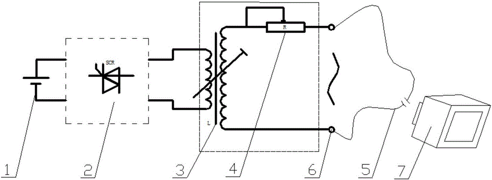
[0029] Such as figure 1 As shown, a method for detecting a breakpoint position of a wire and cable includes: providing high-voltage alternating current; connecting the high-voltage alternating current to the wire and cable 5 under test; observing the entire wire and cable 5 under test with an infrared thermal imager 7, The position of the obvious bright spot found in the imaging of the imager 7 is the breakpoint.

[0030] The inverter device includes a transistor oscillator 2 that can convert direct current int...


PUM


Abstract

The present invention discloses a wire cable breakpoint position detection method. The method comprises: providing high-voltage alternating current; accessing the high-voltage alternating current to a wire cable to be detected; and observing the whole wire cable to be detected in the infrared ray imaging, wherein the position of the obvious bright spot discovered in the infrared ray imaging is a breakpoint position. The wire cable breakpoint position detection method can accurately find the position of the wire cable breakpoint.

Description

technical field [0001] The invention relates to the field of electric wire and cable detection, more specifically, it relates to a method for detecting the breakpoint position of electric wire and cable. Background technique [0002] At present, the detection of wire and cable breakpoints mainly adopts the following three methods: [0003] Induction voltage detection method: use low-voltage alternating current on the broken line, and then use the induction device to detect the change of the induced voltage outside the cable to judge the position of the breakpoint; [0004] Audio monitoring method: pass audio AC signal at one end of the broken line, use the induction device to form capacitive coupling between the broken line, after the signal is amplified, judge the position of the breakpoint by hearing the change of the audio volume in the monitoring earphone; [0005] Capacitance calculation method: use the formula L=UX*S / P (L is the disconnection distance, S is the cable ...

Claims


Application Information

Patent Timeline
IPC IPC(8): G01R31/08G01N25/72
CPCG01R31/083G01N25/72
Inventor 梁鹏陈启先陈国局蓝仁义刘继宇
Owner GUANGXI YUCHAI MASCH CO LTD
Why Eureka
Try Eureka