
New energy and electric power matched city electricity-saving lighting device

A lighting device and new energy technology, which is applied in the direction of lighting devices, lighting devices, lighting device components, etc., can solve the problems that the light intensity cannot be adjusted, does not conform to sustainable development, does not have energy-saving effects, and prevents excessive The effect of charging damage and stable charging current

Active Publication Date: 2017-01-04
徐州鑫凯科技咨询服务有限公司
View PDF4 Cites 4 Cited by
  • Summary
  • Abstract
  • Description
  • Claims
  • Application Information

AI Technical Summary

Problems solved by technology

[0002] In urban supporting facilities, lighting street lamps are indispensable lighting equipment, providing light to passing vehicles and pedestrians, ensuring the normal operation of traffic, and enabling people to see the road clearly, but the street lamps currently used are all regulated by the same, The lighting control is carried out at the same time, and the light intensity cannot be adjusted. At the same time, it completely relies on the mains power supply for lighting, which has no energy-saving effect and does not meet the requirements of sustainable development. Now there is a need for an energy-saving street lamp that can save energy and can use new energy. solve the above problems

Method used


Image

  • New energy and electric power matched city electricity-saving lighting device
  • New energy and electric power matched city electricity-saving lighting device
  • New energy and electric power matched city electricity-saving lighting device

Examples


Embodiment Construction

[0019] The following will clearly and completely describe the technical solutions in the embodiments of the present invention with reference to the accompanying drawings in the embodiments of the present invention. Obviously, the described embodiments are only some, not all, embodiments of the present invention. Based on the embodiments of the present invention, all other embodiments obtained by persons of ordinary skill in the art without making creative efforts belong to the protection scope of the present invention.

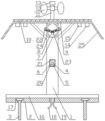
[0020] see Figure 1-4, the present invention provides a technical solution: an urban energy-saving lighting device that combines new energy and electric power, including a hollow column 1, the bottom of the hollow column 1 is provided with a base 2, and a set of feet is mounted on the base 1 Bolt 3, a group of cameras 4 and vibration sensors 5 are provided in the middle of the hollow column 1, a protective cover 6 is provided at the front of the camera 4 and ...


PUM


Abstract

The invention discloses a new energy and electric power matched city electricity-saving lighting device. The new energy and electric power matched city electricity-saving lighting device comprises a hollow stand column, a camera and a vibrating sensor are arranged at the middle portion of the hollow stand column, and a box door is arranged at the upper portion of the hollow stand column; a controller is arranged inside the box door of the hollow stand column, a rain sheltering top cover is arranged at the top of the hollow stand column, and solar panels are paved at the upper portion of the rain sheltering top cover; a stand column is arranged at the center position of the upper portion of the rain sheltering top cover, a wind power generation device is arranged on the stand column, and an illuminance sensor is arranged at the top end of the stand column; and a set of outer lighting lamp and inner light lamp are arranged at the lower portion of the rain sheltering top cover. By means of the new energy and electric power matched city electricity-saving lighting device, automatic lighting can be achieved, automatic lighting and automatic lighting brightness adjustment can be carried out according to practical situations, and the functions of lighting and rain sheltering are achieved; and meanwhile, the remote warning function is achieved, use is safe and reliable, two kinds of new energy including the solar energy and the wind energy can be used, and electricity saving and environmental protection are achieved.

Description

technical field [0001] The invention relates to the field of electric lighting equipment, in particular to an urban power-saving lighting device that combines new energy and electric power. Background technique [0002] In urban supporting facilities, lighting street lamps are indispensable lighting equipment, providing light to passing vehicles and pedestrians, ensuring the normal operation of traffic, and enabling people to see the road clearly, but the street lamps currently used are all regulated by the same, The lighting control is carried out at the same time, and the light intensity cannot be adjusted. At the same time, it completely relies on the mains power supply for lighting, which has no energy-saving effect and does not meet the requirements of sustainable development. Now there is a need for an energy-saving street lamp that can save energy and can use new energy. Solve the above problems. Contents of the invention [0003] The object of the present inventio...

Claims


Application Information

Patent Timeline
Patent Type & Authority Applications(China)
IPC IPC(8): F21S9/02F21S9/03F21S9/04F21V23/00F21V23/04F21V33/00F21V15/00F21W131/103
CPCY02B20/72F21S9/026F21S9/035F21S9/043F21V15/005F21V23/003F21V23/0464F21V23/0485F21W2131/103
Inventor 李从宾
Owner 徐州鑫凯科技咨询服务有限公司
Learn More