Powder blower fixing frame

A powder sprayer and fixed frame technology, which is applied in the direction of supporting machines, machine tables/supports, mechanical equipment, etc., can solve the problems of reduced operating efficiency, inconvenient picking and placing of the powder sprayer, and low efficiency of two-handed operation, and achieve stable positioning Reliable, easy to pick and place, convenient transfer effect

Active Publication Date: 2017-01-04
苏州农业药械有限公司
View PDF7 Cites 0 Cited by
  • Summary
  • Abstract
  • Description
  • Claims
  • Application Information

AI Technical Summary

Problems solved by technology

[0002] The existing powder sprayer fixing frame is provided with a column, and the upper and bottom positions of the column are correspondingly fixed with a positioning ring structure, and the powder sprayer is inserted into the two positioning ring structures from top to bottom, so that the position of the powder sprayer In the actual operation process, when the powder sprayer needs to be transported, it needs to be transported together with the powder sprayer fixing frame. At this time, personnel can only carry the entire structure with both hands. This structure makes the operation efficiency of personnel with both hands low, and then The entire operation efficiency is reduced, and when the powder sprayer needs to be taken out from the powder sprayer fixing frame, the entire powder sprayer needs to be separated from the upper positioning ring from bottom to top, and then moved away from the powder sprayer fixing frame, so that the powder sprayer It is inconvenient to take and place; and the existing powder sprayer fixing frame cannot provide a reliable fixed state during the handling process, making the existing powder sprayer fixing frame applicable to a small range

Method used


Image

  • Powder blower fixing frame
  • Powder blower fixing frame
  • Powder blower fixing frame

Examples


specific Embodiment

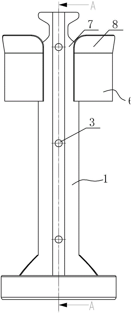
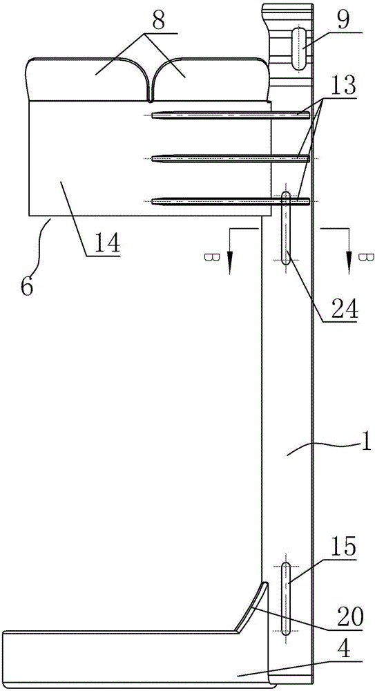
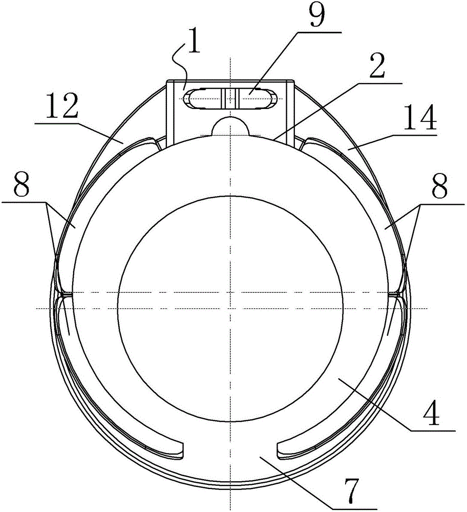
[0034] Specific examples: see figure 2 , Figure 5 , Figure 9 The two side walls 23 of the column 1 are respectively provided with an upper cable tie positioning hole 24 and a lower cable tie positioning hole 15 corresponding to the position between the bottom positioning ring 4 and the upper positioning snap ring 6, and the upper cable tie 16 runs through the two positions respectively. The upper cable tie positioning hole 24 on the side wall and the lower cable tie 17 respectively pass through the lower cable tie positioning holes 15 located on the two side walls. The shapes of the upper cable tie 16 and the lower cable tie 17 can be adjusted arbitrarily according to the powder sprayer to be fixed , when the powder sprayer is fixed, the upper cable tie 16 and the lower cable tie 17 are arranged close to the human body or the structure to be fixed; the upper cable tie positioning hole 24 and the lower cable tie positioning hole 15 are specifically long slot structures para...


PUM


Abstract

The invention provides a powder blower fixing frame. By means of the powder blower fixing frame, taking and putting of a powder blower from the interior of the fixing frame are convenient, the whole fixing frame together with the powder blower are convenient to carry by people, it is guaranteed that transport of the powder blower is convenient, the powder blower can be positioned through the bottom of a stand column, and it is guaranteed that positioning of the powder blower is stable and reliable. The end face, facing the powder blower, of the stand column is particularly an arc-shaped end face which makes the outer wall of the powder blower tightly attached to the corresponding end face of the stand column, the position, facing the powder blower, of the bottom of the stand column is provided with a bottom positioning ring, the bottom positioning ring is provided with a base plate, an upper portion positioning clamping ring is fixedly installed on the position, facing the powder blower, of the middle upper portion of the stand column, a notch is formed in the position, located on the front end face of the powder blower, of the upper portion positioning clamping ring, the back of the upper portion positioning clamping ring is tightly fixed to the end face, back to the powder blower, of the stand column, the upper end of the upper portion positioning clamping ring is provided with a guide piece structure expanding outwards, the upper end of the top of the stand column is provided with a nylon buckle slot, and a nylon buckle with a nylon woven tape is installed in the nylon buckle slot in a buckled mode.

Description

technical field [0001] The invention relates to the technical field of powder sprayer structure, in particular to a powder sprayer fixing frame. Background technique [0002] The existing powder sprayer fixing frame is provided with a column, and the upper and bottom positions of the column are correspondingly fixed with a positioning ring structure, and the powder sprayer is inserted into the two positioning ring structures from top to bottom, so that the position of the powder sprayer In the actual operation process, when the powder sprayer needs to be transported, it needs to be transported together with the powder sprayer fixing frame. At this time, personnel can only carry the entire structure with both hands. This structure makes the operation efficiency of personnel with both hands low, and then The entire operation efficiency is reduced, and when the powder sprayer needs to be taken out from the powder sprayer fixing frame, the entire powder sprayer needs to be separ...

Claims


Application Information

Patent Timeline
Patent Type & Authority Applications(China)
IPC IPC(8): F16M13/04F16M11/04F16M11/16
CPCF16M11/041F16M11/16F16M13/04
Inventor 吕鸣季国炜周洪昌王晓哲黄建清
Owner 苏州农业药械有限公司
Why Eureka
Try Eureka