
Mesh correcting tool

A technology of tooling and mesh, which is applied in the field of synchronous correction tooling of front mesh and side mesh for injection molding, can solve problems such as deflection of injection molding mesh, and achieve the effect of solving deflection and accurate position

Active Publication Date: 2017-01-04
GOERTEK INC
View PDF6 Cites 2 Cited by
  • Summary
  • Abstract
  • Description
  • Claims
  • Application Information

AI Technical Summary

Problems solved by technology

[0003] In view of the above defects, the technical problem to be solved by the present invention is to provide a mesh correction tool, which can simultaneously correct the front mesh and the side mesh, effectively solving the problem of the deflection of the injection molding mesh, Greatly improved the yield of injection molding products

Method used


Image

  • Mesh correcting tool
  • Mesh correcting tool

Examples


Embodiment Construction

[0019] Below in conjunction with accompanying drawing and embodiment, further elaborate the present invention.

[0020] The orientations involved in this manual are all based on the orientation of the mesh calibration tool of the present invention when it is in normal operation, and do not limit its orientation during storage and transportation. It only represents a relative positional relationship, not an absolute positional relationship.

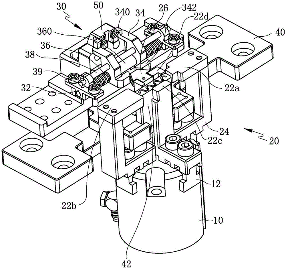
[0021] Such as figure 1 As shown, a mesh correction tool includes a front mesh correction mechanism 20 and a side mesh correction mechanism 30 linked with the front mesh correction mechanism 20 .

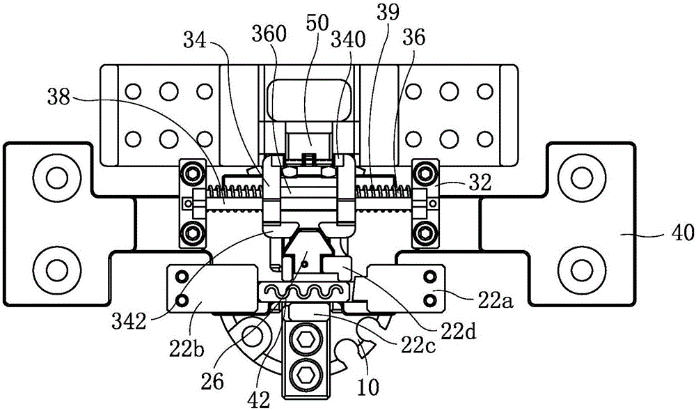
[0022] Such as figure 1 and figure 2 Commonly shown, the front mesh correction mechanism 20 includes a four-claw cylinder 10, and each of the four cylinder claws 12 of the four-claw cylinder 10 is equipped with a front mesh correction claw 22a, 22b, 22c and 22d, and the four front mesh The correction claws 22 a , 22 b , 22 c and 22 d are res...


PUM


Abstract

The invention discloses a mesh correcting tool and relates to the technical field of injection molding tools. The mesh correcting tool comprises a front-side mesh correcting mechanism and a lateral-side mesh correcting mechanism. The front-side mesh correcting mechanism comprises four front-side mesh correcting jaws respectively located on the periphery of a front-side mesh sucker, the four front-side mesh correcting jaws open and close by the aid of power provided by a four-jaw air cylinder, and a linkage block is connected to one of the four front-side mesh correcting jaws. The lateral-side mesh correcting mechanism comprises lateral-side mesh correcting jaws arranged on two sides of a lateral-side mesh sucker, a linkage part matched with the linkage block is arranged at the end of each of the two lateral-side mesh correcting jaws, the linkage parts and the linkage block are coordinated to allow the two lateral-side mesh correcting jaws to open and close, a limit rod transversely penetrates the two lateral-side mesh correcting jaws, and a return spring is arranged on the limit rod. The mesh correcting tool has the advantages that front-side mesh and lateral-side mesh can be corrected at the same time, injection molding product yield is increased greatly, a large amount of manpower and material resources are saved, and enterprise production cost is lowered.

Description

technical field [0001] The invention relates to the technical field of injection molding tooling, in particular to a synchronous correction tooling for front mesh cloth and side mesh cloth for injection molding. Background technique [0002] Injection molding process refers to the process of making molten raw materials into products of a certain shape through operations such as pressurization, injection, cooling, and detachment. There are many types of injection molding products, and there are pure plastic products with a slightly simpler process and mold structure. , There are also products with inserts with complex process and mold structure, and mesh cloth is the most common insert. During injection molding, a manipulator is required to transfer the mesh from the feeding tooling to the injection mold. After the injection molding is completed, the periphery of the mesh will be wrapped in the injection plastic, thereby injecting the mesh onto the plastic product. However, ...

Claims


Application Information

Patent Timeline
Patent Type & Authority Applications(China)
IPC IPC(8): B29C53/18B29C53/80
CPCB29C53/18B29C53/80
Inventor 李德运张烨刘佳张华贞孙伟洋朱宝军庄海涛屈圣玉
Owner GOERTEK INC
Learn More