
IC card surface information marking and positioning method and device

A positioning device and a positioning method technology, applied in auxiliary devices, laser welding equipment, auxiliary welding equipment, etc., can solve the technical limitations of the card surface information marking station, can not substantially improve the utilization rate of laser machines, and restrict the development of card making equipment and other problems, to achieve the effect of reducing power source and supporting electrical equipment, improving laser utilization rate, and improving laser utilization efficiency

Active Publication Date: 2017-01-04
沈阳友联电子装备有限公司
View PDF7 Cites 2 Cited by
  • Summary
  • Abstract
  • Description
  • Claims
  • Application Information

AI Technical Summary

Problems solved by technology

[0003] At present, the development of personalized data writing equipment is limited by the technology of the card surface information marking station, and has entered a development bottleneck. By compressing the takt time to increase the mechanical speed, it has been impossible to substantially increase the utilization rate of the laser machine, thus restricting the development of card making equipment. , it is urgent to find a breakthrough point from the beat setting

Method used


Image

  • IC card surface information marking and positioning method and device
  • IC card surface information marking and positioning method and device
  • IC card surface information marking and positioning method and device

Examples


Embodiment Construction

[0033] In order to make the object, technical solution and advantages of the present invention clearer, the present invention will be described in detail below in conjunction with the accompanying drawings and specific embodiments.

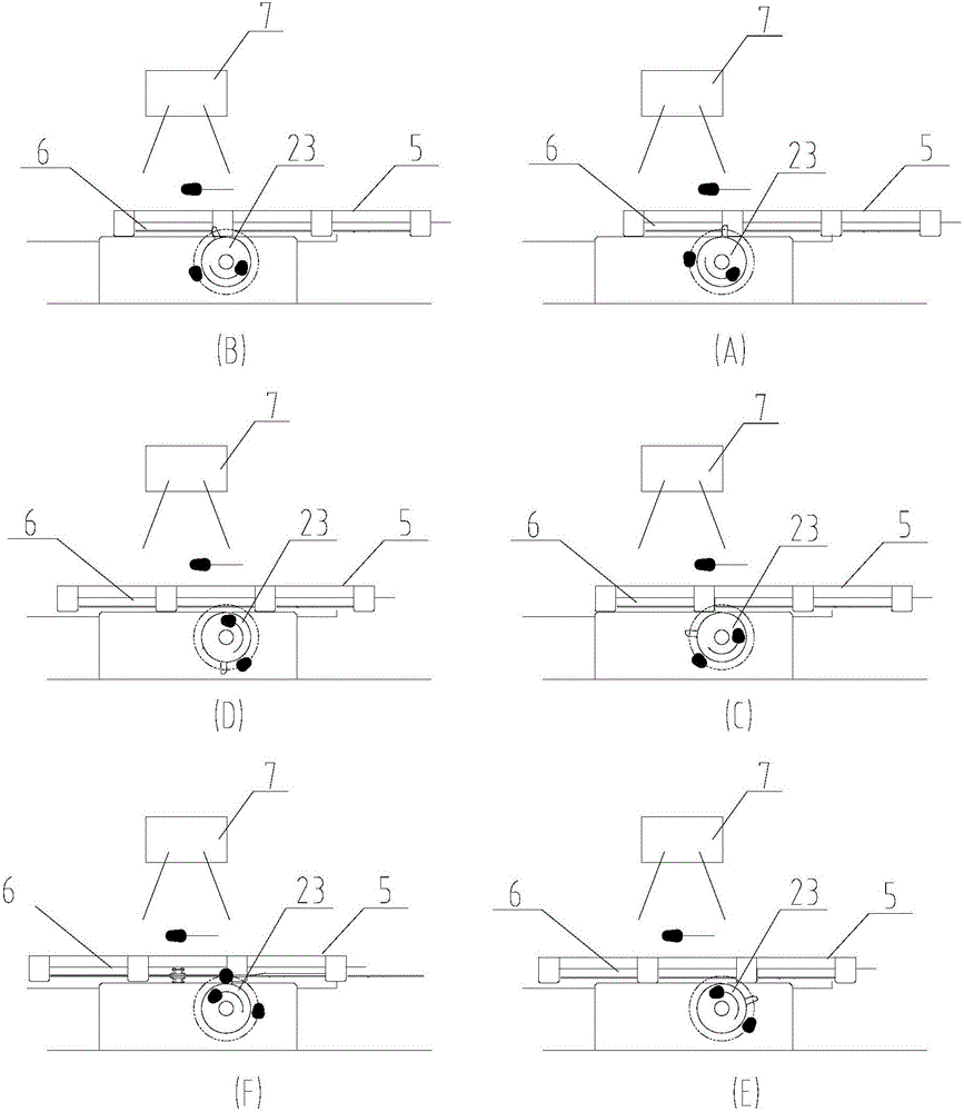
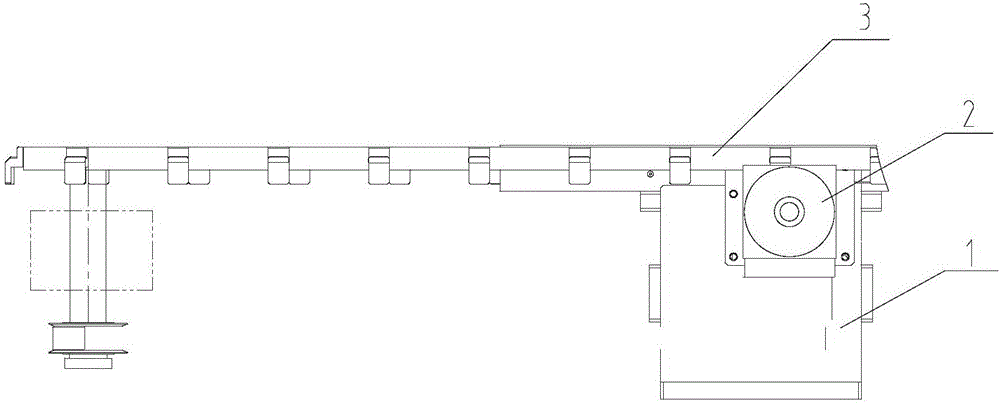
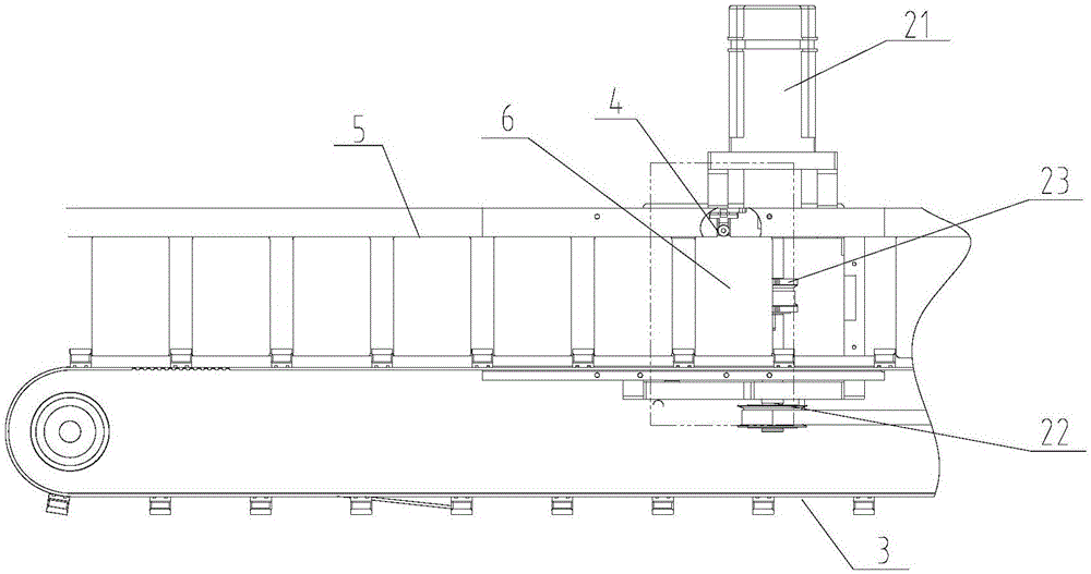
[0034] Such as Figure 1-2 As shown, a method for marking and positioning IC card card surface information, the card 6 is transported forward by the card transport belt 3, and is limited by the stoppers arranged on the card transport belt 3, and the two ends of the card 6 are controlled by the supporting card. 5 guide, after the card 6 is transported to the IC card surface information marking station, the card 6 is moved by the rotating positioning fork 23 to be close to the stopper on the card transmission belt 3, so that the card 6 enters on the card transmission belt 3 Positioning in the feeding direction; the card 6 is positioned vertically in the feeding direction of the card transport belt 3 through the card pretensioning mechanism 4 arrange...


PUM


Abstract

The invention belongs to the technical field of IC card making, and particularly discloses an IC card surface information marking and positioning method and device. The method includes the steps of forward conveying cards through a card conveying belt, limiting the cards through stop pieces arranged on the card conveying belt, guiding the two ends of each card through card supporting ways, shifting the cards through a rotary positioning shifting fork to get close to the stop pieces on the card conveying belt after the cards are conveyed into an IC card surface information marking station so that the cards can be positioned in the feeding direction of the card conveying belt, and positioning the cards in the direction perpendicular to the feeding direction of the card conveying belt through card pre-tightening mechanisms arranged in the card supporting ways. By saving card positioning rhythms, the utilization rate of a card information marking device host is increased, and the whole machine yield is greatly improved.

Description

technical field [0001] The invention belongs to the technical field of IC card making, and in particular relates to a method for marking and positioning IC card surface information and a device thereof. Background technique [0002] The size of the IC card is 85.6mm×54mm in accordance with the national unified standard. The card base material of the IC card is PVC (polyvinyl chloride), ABS and other plastics or paper. Currently, the information on the IC card surface is marked on the IC card personalization equipment. The positioning method is: main belt stepping + card positioning and clamping + laser marking + card positioning reset or main belt stepping + card positioning and clamping and then reset + laser marking. It takes at least three Or more than three beats, too many auxiliary beats, which seriously restricts the utilization efficiency of the laser machine, the core component of the card surface information marking equipment, forcing the utilization rate to be no h...

Claims


Application Information

Patent Timeline
Patent Type & Authority Applications(China)
IPC IPC(8): B23K26/60B23K26/70B23K37/04B23K26/362
CPCB23K26/361B23K26/60B23K26/70B23K26/702B23K37/0426
Inventor 唐广文
Owner 沈阳友联电子装备有限公司
Learn More