Circulating fluidized bed flue gas desulfurization apparatus

A technology of circulating fluidized bed and desulfurization device is applied in the field of flue gas purification, which can solve the problems of increasing the operation and maintenance cost of the device, easy blockage, and large resistance reduction.

Active Publication Date: 2017-01-04
CHINA PETROLEUM & CHEM CORP +2
View PDF7 Cites 4 Cited by
  • Summary
  • Abstract
  • Description
  • Claims
  • Application Information

AI Technical Summary

Problems solved by technology

In the prior art, the flue gas dust concentration at the top of the desulfurization tower is as high as (800-1100g / Nm 3 ), which brings greater difficulty to the subsequent gas-solid separation facilities, causing increased investment and increased operating costs, especially the frequent backflushing of the dust collector due to the high dust concentration, which leads to short operating cycles and high operating costs of the dust collector. question
For example, CN10402019 A discloses a flue gas desulfurization technology of a reflux circulating fluidized bed in a uniform flow field. The flow rate of the internal gas phase is low, and the tangential velocity generated by the swirl plate is low. It is difficult to achieve a good separation of the gas-solid two-phase, and the structure of the swirl plate is complex, and the resistance drop of the gas-solid two-phase passage is large.
[0004] There are two methods for existing flue gas gas-solid separation facilities: the first method is that the flue gas directly enters the dust collector, and the gas-solid separation is completely realized through the dust collector, such as a high-efficiency circulating fluidized bed device disclosed in CN203507814 U. The flue gas of the fluidized bed device is ejected from the reactor and directly enters the dust collector. However, due to the high particle concentration, the load of the dust collector is large, it is easy to block and the resistance drop is large, resulting in a large size of the dust collector, increasing investment, and frequent blowback of the dust collector , which increases operating costs and can easily shorten the operating cycle of the dust collector; the second way is to add an external gas-solid separator in front of the dust collector to pre-separate the gas-solid two-phase, reduce the dust content of the flue gas and reduce the workload of the dust collector , but because the addition of an external gas-solid separator increases the complexity of the process, increases the flow resistance of the flue gas, and increases the pressure drop of the system, which increases the investment and construction costs of the device, and also increases the operation and maintenance costs of the device

Method used


Image

  • Circulating fluidized bed flue gas desulfurization apparatus
  • Circulating fluidized bed flue gas desulfurization apparatus

Examples


Embodiment Construction

[0029] Specific embodiments of the present invention will be described in detail below in conjunction with the accompanying drawings. It should be understood that the specific embodiments described here are only used to illustrate and explain the present invention, and are not intended to limit the present invention.

[0030] In the present invention, in the absence of a contrary statement, the orientation words used such as "upper, lower," are based on the flow direction of the flue gas in the reaction tower when the circulating fluidized bed flue gas desulfurization device works normally. Specifically, the flow direction towards the smoke is up, and the direction away from the flow of the smoke is down. "Inside and outside" refer to the inside and outside of the corresponding component contours. In addition, the arrow directions in the drawings represent the smoke direction of flow.

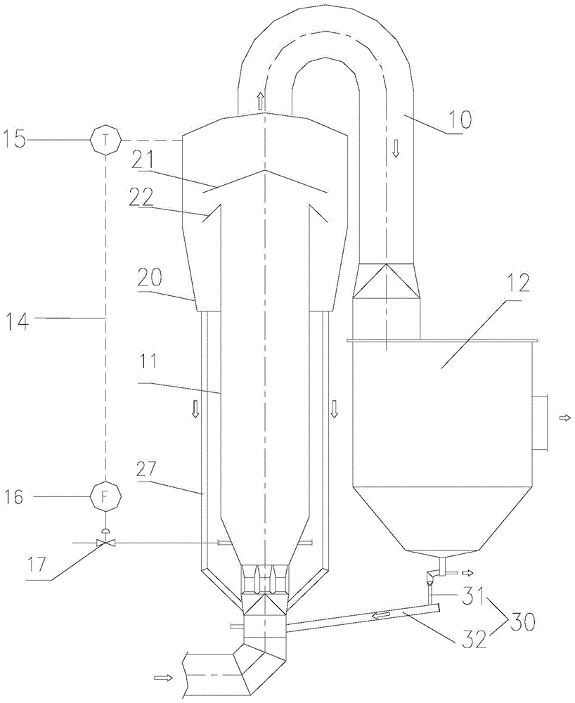
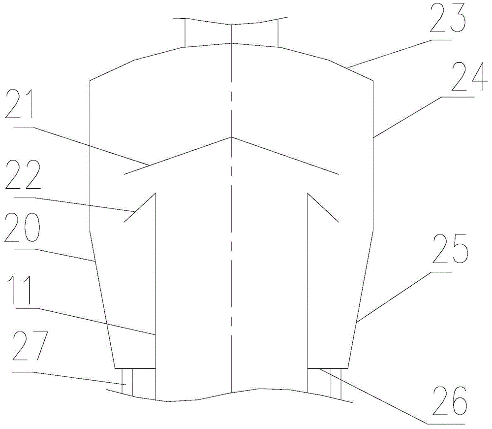
[0031] Such as Figure 1 to Figure 2 As shown, the present invention provides a circulati...


PUM

PropertyMeasurementUnit
Cone angleaaaaaaaaaa
Angleaaaaaaaaaa

Abstract

The present invention discloses a circulating fluidized bed flue gas desulfurization apparatus, which comprises a reaction tower and a dust remover, wherein the reaction tower and the dust remover are communicated through an outlet flue channel, the reaction tower and the outlet flue channel are communicated through a settler, the settler forms a closed shield covering on the outlet channel of the reaction tower, an ash blocking baffle is fixedly arranged inside the settler and blocks above the free end of the outlet channel, a gap for communicating the closed shield and the outlet channel is formed between the ash blocking baffle and the free end, the outlet channel is circumferentially provided with an anti-backmixing plate, and an opening channel is formed between the anti-backmixing plate and the ash blocking baffle, and obliquely and downwardly extends. According to the present invention, with the ash blocking baffle arranged inside the settler and the anti-backmixing plate arranged on the reaction tower, the two flue gas dust fall can be achieved, the dust concentration of the flue gas entering the dust remover can be reduced, and the work load of the dust remover can be reduced.

Description

technical field [0001] The invention relates to the technical field of flue gas purification, in particular to a circulating fluidized bed flue gas desulfurization device. Background technique [0002] Circulating fluidized bed flue gas desulfurization is based on the principle of circulating fluidized bed. Through multiple cycles of absorbent, the contact time between absorbent and flue gas is prolonged, and the utilization rate of absorbent is improved. The desulfurization technology belongs to dry or semi-dry desulfurization technology. With the continuous development of technology, the desulfurization rate of this desulfurization method has approached or reached the desulfurization efficiency of the wet process, and the desulfurization efficiency has reached more than 90%. The main advantages of this technology are: simple process, less engineering investment, small footprint, high utilization rate of desulfurization agent, less corrosion of equipment and pipelines, no ...

Claims


Application Information

Patent Timeline
IPC IPC(8): B01D53/83B01D53/48B01D45/08B01D45/04B01D45/02
Inventor 吴德飞孙丽丽李浩周桂娟黄小平江盛阳饶隽
Owner CHINA PETROLEUM & CHEM CORP
Why Eureka
Try Eureka