
Patsnap Eureka
For R&D, Patsnap Eureka makes reading and utilizing patents & technical documents easy.
Patsnap Eureka AIR
Designed for self-driven R&D workflows. Generate viable solutions, solve complex R&D challenges, empower your innovation with AI.

Patsnap Eureka Materials
Designed for material experts only. Revolutionize your material R&D, from search, analyze, to developing new materials.

TechResearch
Generate reliable direction feasibility study reports for your R&D in just a few steps.

TechSeek
Discover and master advanced knowledge NOW. Basics, ideas, possibilities, all at once.

TechMind
As an expert in R&D Theories, TechMind can generates customized viable solutions instantly.

TechRisk
Analyze your overall solution with one click, know your potential R&D risks in advance.

TechMonitor
Get weekly tech updates, stay abreast of the latest tech innovations and key insights.
Material management system and method for hot-rolled steel plate
A hot-rolled steel plate and management system technology, which is applied in metal rolling, metal rolling, rolling mill control devices, etc., to achieve the effect of improving the factory yield
- Summary
- Abstract
- Description
- Claims
- Application Information
AI Technical Summary
Problems solved by technology
Method used
Image

Examples
Embodiment 1
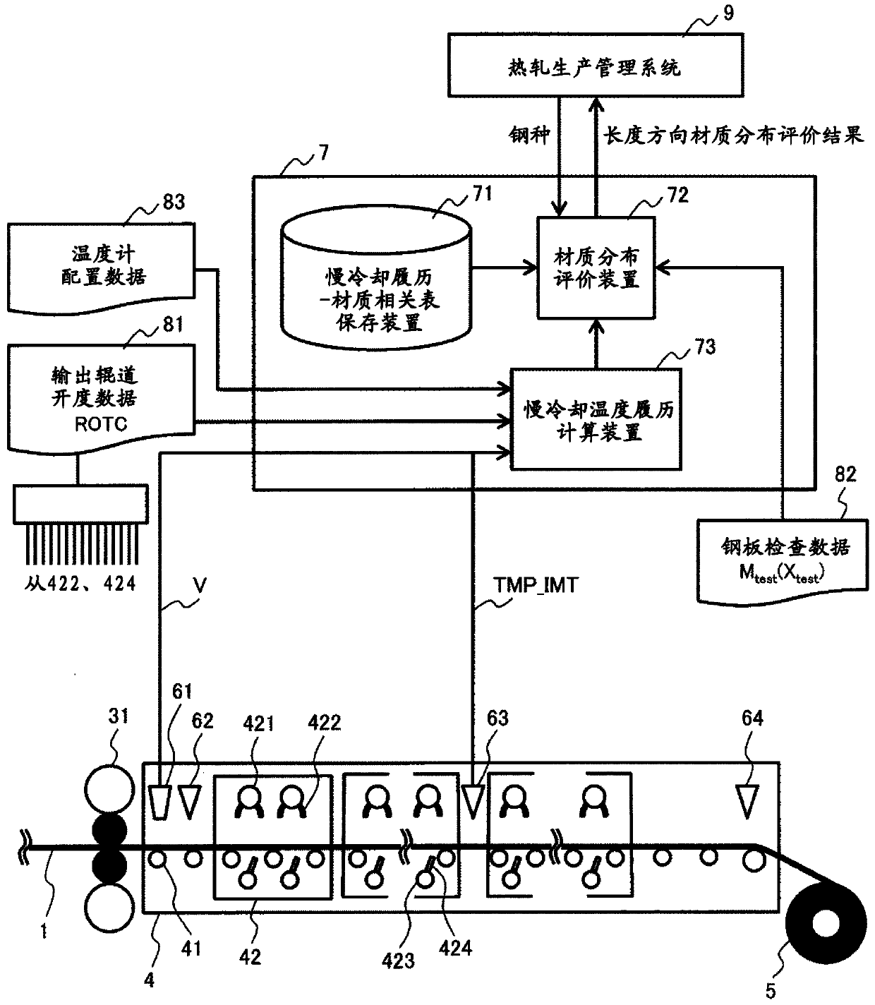
[0032] Hereinafter, Embodiment 1 of the present invention will be described. first, figure 1 It is a figure which shows the facility structure of the finish rolling stage of the hot rolling facility of Example 1 of this invention.
[0033] exist figure 1 In the finish rolling stage of the shown hot rolling equipment, the steel plate 1 is rolled in the final stand 31 of the finish rolling mill, passes through the run-out table 4, and is then coiled by the coiler 5 . Such a structure is a known structure. In the output roller table 4 , the steel plate 1 is placed on conveying rollers 41 and passes through a plurality of cooling beds 42 . Each cooling bed 42 has a plurality of cooling heads 421 , and each cooling head 421 also has a plurality of cooling nozzles 422 . Each cooling bed 42 also has a plurality of lower surface cooling heads 423 , and each lower surface cooling head 423 has a plurality of lower surface cooling nozzles 424 .
[0034] In order to cool the steel pl...
Embodiment 2
[0119] Figure 13 shows other embodiments of the present invention. Embodiment 1 described above is carried out using the output of the temperature detection device 654 instead of the intermediate thermometer 63 whose position is fixed. The plurality of collectors 651 arranged on the output roller table 4 collect the light emitted from the steel plate 1 at a plurality of positions on the output roller table 4 . The collected light is input to the switching device 653 via the optical beam 652 . The switching device 653 selects the collection part 651 collected by the collection part 651 with the smallest separation distance among the collection parts 651 separated from the position of the cooling head 421 that discharges the cooling water toward the winding device 5 side by a distance greater than or equal to the strip-shaped water disappearance distance L_X. light, and output it to the temperature detection device 654. The temperature detection device 654 interprets the lig...
Embodiment 3
[0122] Figure 14 shows another embodiment of the present invention. Embodiment 1 described above was carried out using the output of the non-contact thermometer 661 movable in the longitudinal direction of the steel plate 1 by the moving rail 662 instead of the intermediate thermometer 63 at a fixed position. The non-contact thermometer 661 measures the temperature of the steel plate 1 at a position away from the cooling head 421 where the cooling water is discharged toward the coiler 5 side by the strip water disappearance distance L_X. The technique of this example is more complicated than that of Example 1, but it has the effect of improving the calculation accuracy of the slow cooling history by measuring at a position close to the slow cooling start temperature TMP_SS. In addition, compared with Example 2, maintenance becomes complicated due to the addition of moving parts, but there is an effect that the temperature of the steel plate 1 is measured at a position closer...
PUM
 Abstract
Description
Claims
Application Information
 - R&D Engineer
- R&D Manager
- IP Professional
- Industry Leading Data Capabilities
- Powerful AI technology
- Patent DNA Extraction
Browse by: Latest US Patents, China's latest patents, Technical Efficacy Thesaurus, Application Domain, Technology Topic, Popular Technical Reports.
© 2024 PatSnap. All rights reserved.Legal|Privacy policy|Modern Slavery Act Transparency Statement|Sitemap|About US| Contact US: help@patsnap.com