Cutting machine

A cutting machine and control mechanism technology, used in metal processing machinery parts, maintenance and safety accessories, metal processing equipment, etc., can solve problems such as single function, low cutting efficiency, and complex cutting machine structure.

Inactive Publication Date: 2016-12-21
洪义英
View PDF5 Cites 1 Cited by
  • Summary
  • Abstract
  • Description
  • Claims
  • Application Information

AI Technical Summary

Problems solved by technology

[0002] Cutting machines are widely used in industrial machinery to cut steel and other workpieces. The existing cutting machines do not have a walking mechanism. The cutter wheel and transmission device are directly installed on the frame. When using, the cutting machine needs to be placed on the ground. Or on the station, move the workpiece to the position where the cutting machine is located. This kind of cutting machine is more convenient when cutting smaller workpieces, but when it is necessary to cut large workpieces or perform mobile cutting, the cutting range will be limited. , Unsteady walking and inconvenient cutting
[0003] The existing cutting machine has a complex structure and a single function. It can only cut horizontally, and the cutting direction cannot be adjusted. It is inconvenient to use, the cutting efficiency is not high, and the cutting debris is scattered everywhere, making the working environment messy.

Method used


Image

  • Cutting machine

Examples


Embodiment Construction

[0009] Below in conjunction with accompanying drawing, the present invention will be further described.

[0010] In order to make the object, technical solution and advantages of the present invention clearer, the present invention will be further described in detail below in conjunction with the accompanying drawings and specific embodiments. It should be understood that the specific embodiments described here are only used to explain the present invention, and are not intended to limit the present invention.

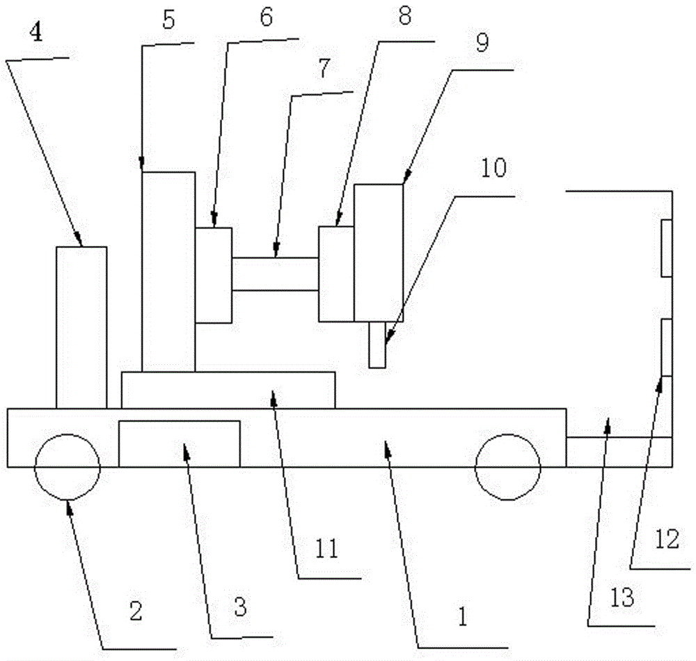
[0011] Such as figure 1 As shown, the specific embodiment adopts the following technical scheme: it includes a base 1, a wheel 2, a motor 3, a control mechanism 4, a vertical slide rail 5, a slider 6, a connecting block 7, a rotating disk 8, an upper cover 9, a blade 10. Horizontal slide rail 11, magnet 12, storage space 13; the two ends of the base 1 are provided with wheels 2, the base 1 is provided with a motor 3, the upper cover 9 and the blade 10 form a cutting t...


PUM


Abstract

The invention discloses a cutting machine and relates to the field of machinery. The cutting machine comprises a base, vehicle wheels, a motor, a control mechanism, a vertical slide rail, slide blocks, a connection block, a rotating disc, an upper cover, a blade, a horizontal slide rail, magnets and a containing space. The vehicle wheels are arranged at the two ends of the base. The motor is arranged in the base. The upper cover and the blade constitute a cutting tool. The cutting tool is arranged on the rotating disc. The rotating disc is connected with the corresponding slide block through the connection block. The corresponding slide block is connected with the vertical slide rail. Another slide block is arranged below the vertical slide rail, and the vertical slide rail is connected with the horizontal slide rail through the corresponding slide block. The horizontal slide rail and the control mechanism are both arranged on the base. The control mechanism is arranged at the left end of the vertical slide rail. The containing space is formed in the right end of the base. The magnets are arranged on the vertical face of the right end of the containing space. The cutting machine has the beneficial effects that the cutting direction can be adjusted at will; all-dimensional cutting can be conducted conveniently; cutting efficiency is high; metal chippings obtained after cutting can be collected in a centralized manner; and the cutting work environment can be tidy and clean.

Description

technical field [0001] The invention relates to the field of machinery, in particular to a cutting machine. Background technique [0002] Cutting machines are widely used in industrial machinery to cut steel and other workpieces. The existing cutting machines do not have a walking mechanism. The cutter wheel and transmission device are directly installed on the frame. When using, the cutting machine needs to be placed on the ground. Or on the station, move the workpiece to the position where the cutting machine is located. This kind of cutting machine is more convenient when cutting smaller workpieces, but when it is necessary to cut large workpieces or perform mobile cutting, the cutting range will be limited. , Unsteady walking, inconvenient cutting problem. [0003] The existing cutting machine has complex structure and single function, can only cut horizontally, and cannot adjust the cutting direction, which is inconvenient to use, and the cutting efficiency is not high...

Claims


Application Information

Patent Timeline
IPC IPC(8): B23Q5/34B23Q11/00
CPCB23Q5/34B23Q11/0064
Inventor 洪义英
Owner 洪义英
Why Eureka
Try Eureka