Die bonding device

A crystal bonding device and reaction technology, which is applied in the direction of semiconductor devices, electrical components, circuits, etc., can solve the problems of center of gravity deviation between platform and reaction components, increase of space in the driving direction, and deterioration of weight balance, so as to reduce deviation and prevent Effect of shaking, improving weight balance

Active Publication Date: 2019-09-06
SHINKAWA CO LTD
View PDF2 Cites 0 Cited by
  • Summary
  • Abstract
  • Description
  • Claims
  • Application Information

AI Technical Summary

Problems solved by technology

[0008] However, generally speaking, since the die bonding device is a long stroke (longstroke) with a long moving distance in the driving direction, if the stage and the reaction member are all arranged in the driving direction as in the existing die bonding device, the movement in the driving direction The space will be greatly increased
Moreover, disposing both the platform and the reaction member in the driving direction results in a large shift of the center of gravity of the platform and the reaction member, thereby degrading the weight balance of the pedestal supporting the platform and the reaction member.

Method used


Image

  • Die bonding device
  • Die bonding device
  • Die bonding device

Examples


Embodiment Construction

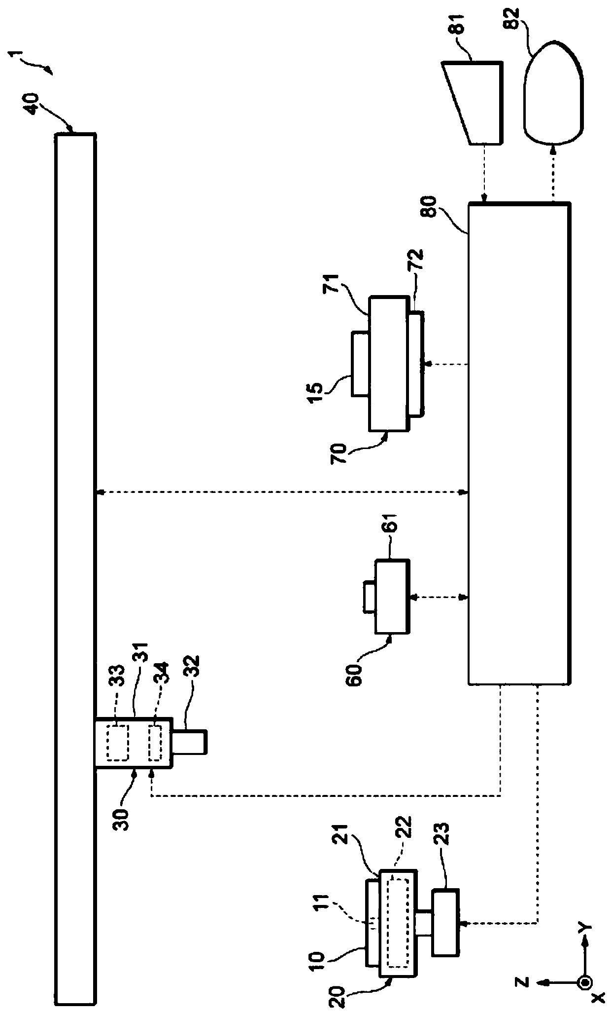
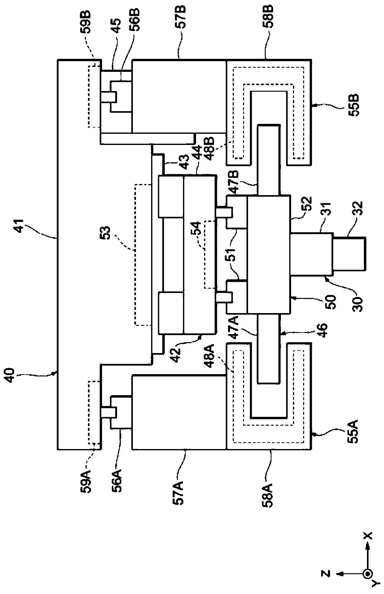
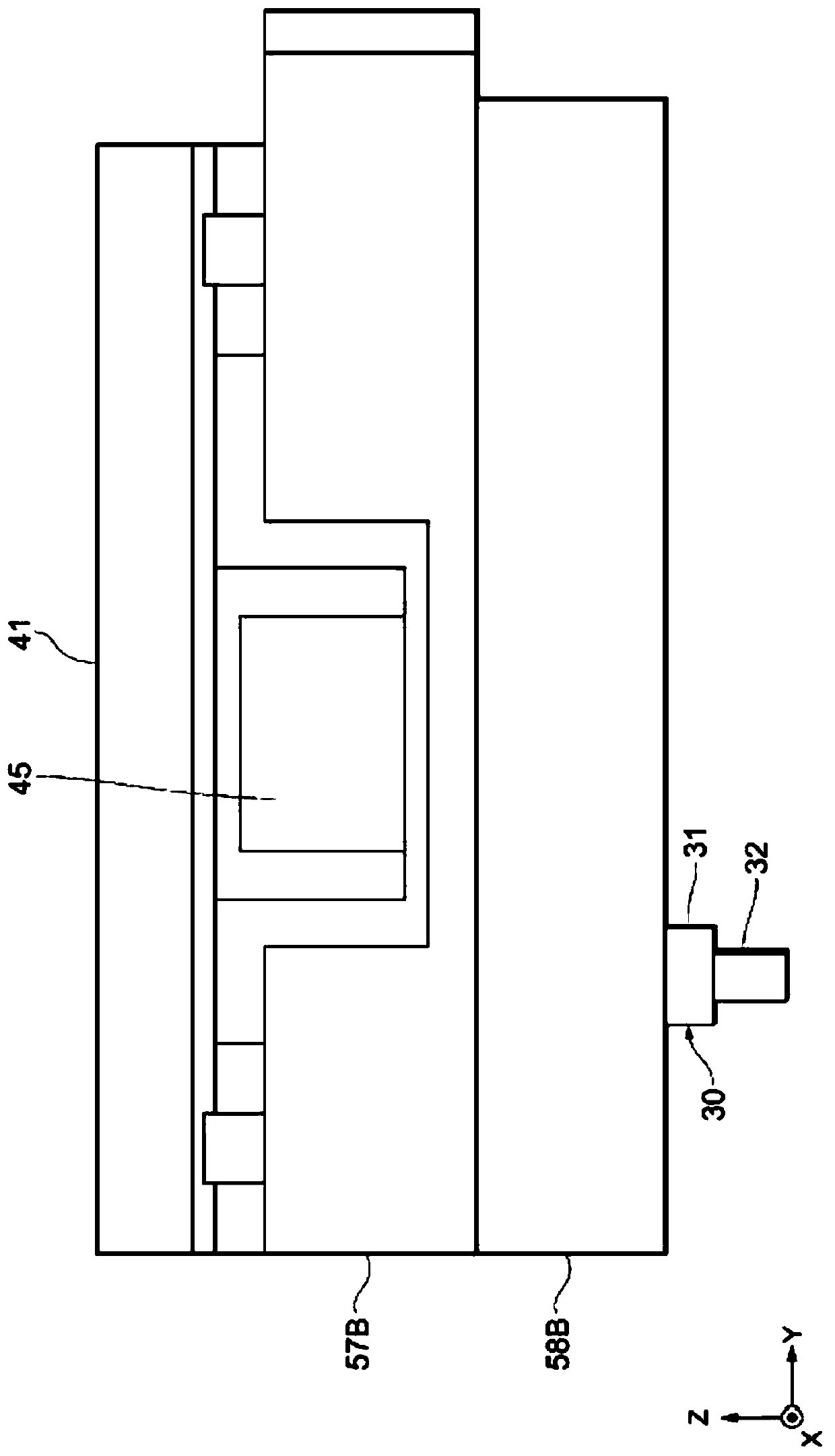
[0073]Embodiments of the present invention will be described below. In the following description of the drawings, the same or similar parts are denoted by the same or similar symbols. However, the drawings are schematic drawings. Therefore, specific dimensions and the like should be determined in consideration of the following description. Furthermore, of course, there are also parts where the relationship or ratio of mutual dimensions differs among the drawings. Furthermore, the technical scope of the invention of the present application should not be limited to the above-described embodiments and should not be interpreted. In addition, in the following description, the upper side of the drawings is referred to as "upper", the lower side is referred to as "lower", the left side is referred to as "left", and the right side is referred to as "right". The direction along and parallel to the X-axis shown in the figure is called the X-axis direction, the direction along the Y-a...


PUM


Abstract

The invention provides a crystal bonding device, comprising: a platform (52), which is arranged to move along the Y-axis direction relative to a pedestal (41); and a first reaction member (58A) and a second reaction member (58B), which are respectively opposite The pedestal is provided so as to be movable in the Y-axis direction; the first reaction member and the second reaction member are configured to move oppositely to the platform in the Y-axis direction when the platform moves in the Y-axis direction, and the first reaction member and the second reaction member The 2 reaction members are arranged on both sides in the X-axis direction with the platform at intervals, and the first reaction member and the second reaction member are arranged so that the center of gravity of the first reaction member and the second reaction member is at a position based on the center of gravity of the platform. . Thereby, there is provided a die bonding apparatus capable of suppressing an increase in space and improving the weight balance in the pedestal.

Description

technical field [0001] Several embodiments of the present invention relate to a die bonding device. Background technique [0002] Conventionally, as such a die bonding device, there is known a die bonding device in which an X-axis linear motor (linear motor) has a coil part including a three-phase coil (coil) as a moving part and a yoke ( yoke) part, the yoke part is fixed to the base (base) (pedestal) through the yoke part guide (guide) that can move in the same axial direction as the coil part, and absorbs the reaction force when the coil part moves; and when moving The lower portion of the table has an XY stage on which an X-axis linear motor is arranged (for example, refer to Patent Document 1). [0003] prior art literature [0004] patent documents [0005] Patent Document 1: Japanese Patent Laid-Open No. 2012-114359 [0006] In the die bonding apparatus of Patent Document 1, the yoke portion moves in the X-axis direction opposite to the coil portion, thereby absor...

Claims


Application Information

Patent Timeline
Patent Type & Authority Patents(China)
IPC IPC(8): H01L21/52H01L21/60
CPCH01L24/75H01L2224/75651H01L2224/75744H01L2224/75745H01L2224/75804H01L2224/75841H01L21/52H01L21/78H01L24/01H01L24/74H01L24/741
Inventor 角谷修田泽秀博辻正人
Owner SHINKAWA CO LTD
Why Eureka
Try Eureka