
Vibration motor

A technology of vibrating motors and vibrating components, applied in the direction of electromechanical devices, electrical components, etc., can solve the problems of weak overall rigidity of vibrating components, complicated production processes, high production costs, etc., to avoid noise and defective products, improve yield, and reduce deformation Effect

Inactive Publication Date: 2016-12-14
AAC TECH PTE LTD
View PDF8 Cites 3 Cited by
  • Summary
  • Abstract
  • Description
  • Claims
  • Application Information

AI Technical Summary

Problems solved by technology

When this structure is adopted, the overall rigidity of the vibrating component is weak, and it is prone to deformation, which in turn is likely to generate additional noise and produce more defective products, resulting in a lower yield
In addition, during assembly, an additional guide plate is required to fix the pole core on the counterweight, resulting in high production costs and complicated production processes

Method used


Image

  • Vibration motor
  • Vibration motor
  • Vibration motor

Examples


Embodiment Construction

[0021] The present invention will be further described below in conjunction with the accompanying drawings and embodiments.

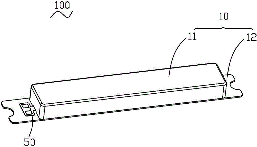
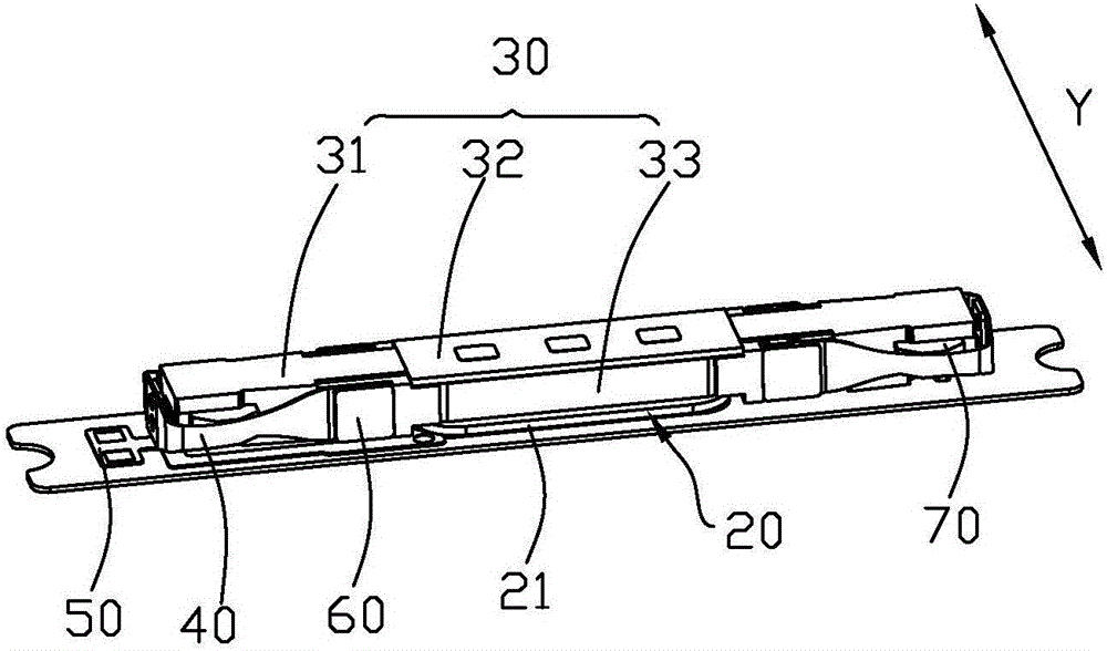
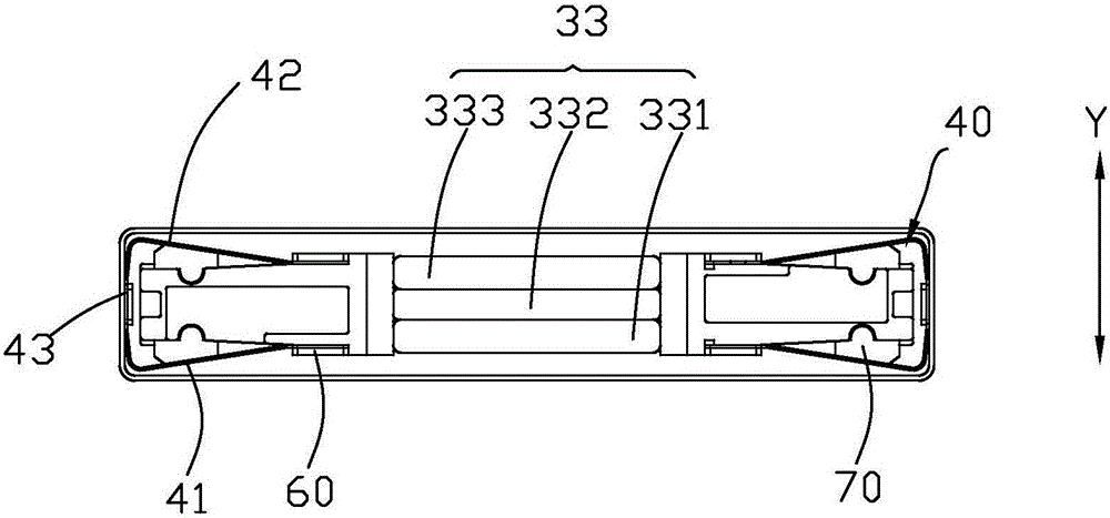
[0022] Figure 1-3 A vibration motor 100 in one embodiment of the present invention is shown. Such as Figure 1-3 As shown, the vibrating motor 100 generally includes a casing 10 with a receiving space (not labeled), and a fixing component 20 , a vibrating component 30 and an elastic connecting member 40 accommodated in the casing 10 . Wherein, the housing 10 includes a housing 11 and a cover plate 12 covering the housing 11 to cooperate with the housing 11 to form a receiving space. The fixing assembly 20 is fixed on the cover plate 12 . The vibrating assembly 30 is suspended in the accommodating space through the elastic connecting piece 40, and along the direction perpendicular to the length direction of the cover plate 12 (see Figure 2-3 In the Y direction) reciprocating vibration. The direction Y is the vibration direction.

[0023] Specific...


PUM


Abstract

The invention provides a vibration motor. The vibration motor comprises a housing, a fixing assembly, a vibration assembly and an elastic connection piece. The fixing assembly is accommodated in the housing. The vibration assembly is arranged in the housing in an suspended manner through the elastic connection piece. The fixing assembly comprises a coil fixed in the housing. The vibration assembly comprises a balancing weight, a pole attached to the balancing weight and a magnetic steel assembly. The balancing weight comprises a first side part, a second side part and a connecting arm connecting the first side part and a second side part. The pole core cooperates with the first side part and the second side part to form an accommodation groove used for accommodating the magnetic steel assembly. The connecting arm is arranged on the accommodating groove. The connecting arm is provided with at least one positioning platform. The pole core is correspondingly provided with at least one positioning hole adapted to the at least one positioning platform. The vibration motor is quite high in rigidity, quite low in noise, quite high in finished product rate and low in production cost.

Description

【Technical field】 [0001] The invention relates to vibration motor technology, in particular, to a vibration motor suitable for portable consumer electronic products. 【Background technique】 [0002] With the development of electronic technology, portable consumer electronic products are becoming more and more popular, such as mobile phones, handheld game consoles, navigation devices or handheld multimedia entertainment equipment, etc. These electronic products generally use vibration motors for system feedback. Such as mobile phone call prompts, information prompts, navigation prompts, vibration feedback of game consoles, etc. [0003] A vibration motor of the related art includes a vibration assembly having a weight and a pole core. Wherein, the counterweight usually includes two side parts, and the two side parts are connected by connecting arms; the pole core is welded on the counterweight. When this structure is adopted, the overall rigidity of the vibrating component i...

Claims


Application Information

Patent Timeline
Patent Type & Authority Applications(China)
IPC IPC(8): H02K33/02
CPCH02K33/02
Inventor 黄金全吴娜邵焱凌芳华
Owner AAC TECH PTE LTD
Learn More