
Access-sensing antenna device and antenna structure thereof

A technology of proximity sensing and antenna device, which is applied in the direction of antenna grounding device, antenna support/installation device, antenna grounding switch structure connection, etc., to achieve the effect of reducing the overall volume and saving costs

Inactive Publication Date: 2016-12-14
YAODENG ELECTRONICS COMM TECH KUNSHAN CO LTD
View PDF9 Cites 14 Cited by
  • Summary
  • Abstract
  • Description
  • Claims
  • Application Information

AI Technical Summary

Problems solved by technology

Furthermore, in order to make the induction more accurate, the conventional antenna device needs to use several proximity sensors or several capacitors with several layers of conductive layers to produce induction in conjunction with the proximity sensor. There is still room for innovation and improvement.

Method used


Image

  • Access-sensing antenna device and antenna structure thereof
  • Access-sensing antenna device and antenna structure thereof
  • Access-sensing antenna device and antenna structure thereof

Examples


Embodiment Construction

[0042] In order to make the above objects, features and advantages of the present invention more comprehensible, specific implementations of the present invention will be described in detail below in conjunction with the accompanying drawings.

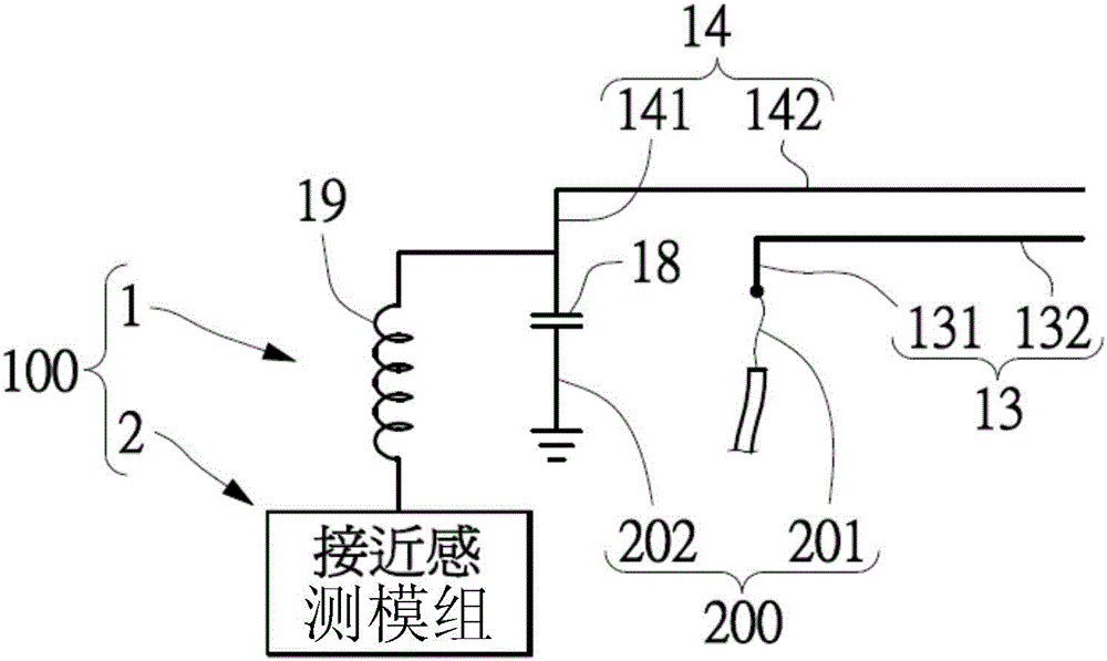
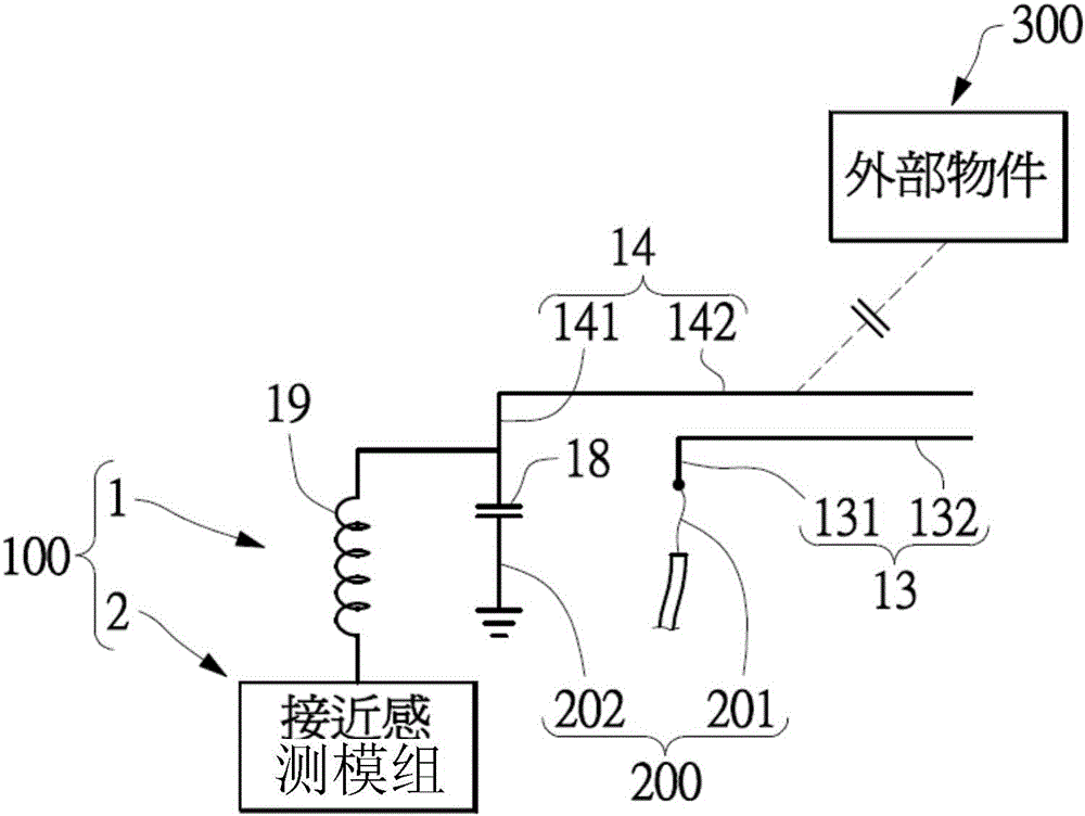
[0043] see figure 1 and figure 2 , which is an embodiment of the present invention. What needs to be explained first is that this embodiment corresponds to the relevant quantities and shapes mentioned in the drawings, which are only used to specifically illustrate the implementation of the present invention, so as to facilitate understanding of its content. It is not intended to limit the scope of rights of the present invention.

[0044] The present embodiment is a proximity-sensing antenna device 100 for installation in an electronic device (not shown), so as to cooperate with a transmission line 200 in the electronic device. Wherein, the above-mentioned electronic device is, for example, a notebook computer, a tablet computer, a...


PUM


Abstract

The invention provides an access-sensing antenna device including an antenna structure and an access sensing modulus. The antenna structure comprises a first and a second conductors, and a capicator assembly and an inductance assembly electrically connected to the second conductor. The second conductor is coupled with the first conductor through RF signals to serve as an capicatance electrode that senses external objects. When the second conductor serves as a capicator electrode, capicatance value that is changed according to distance relative to the external objects is generated. When the capicatance assembly is used for isolating the second conductor to form the capicatance electrode, the capicatance assembly is arranged through the detection signal on the second conductor; and when the inductance assembly, for isolating the first conductor, is coupled to the second conductor, is arranged through the RF signal of the second conductor. The access sensing modulus is electrically connected to the inductance assembly and further is electrically connected to the second conductor and the capicator assembly through the inductance assembly.

Description

[0001] priority [0002] The present invention takes the Taiwan patent whose application date is September 11, 2015 and whose application number is 104130110 as priority. technical field [0003] The present invention relates to an antenna device, and in particular to a proximity sensing antenna device and its antenna structure. Background technique [0004] In order to control the amount of radiation generated by handheld electronic devices on the human body, when designing handheld electronic devices, it is generally necessary to add a proximity sensor (P-sensor) at the main antenna position of the wireless wide area network (WWAN) to sense the human body approach, and then activate the protection mechanism of power reduction to reduce the radiation level generated by the handheld electronic device. Furthermore, in order to make the sensing more accurate, the conventional antenna device needs to use several proximity sensors or several capacitors with several layers of c...

Claims


Application Information

Patent Timeline
Patent Type & Authority Applications(China)
IPC IPC(8): H01Q1/22H01Q1/24H01Q1/50H01Q1/48H01Q1/38G01D5/24
CPCG01D5/24H01Q1/22H01Q1/242H01Q1/38H01Q1/48H01Q1/50
Inventor 阮鹏豪黃佑综
Owner YAODENG ELECTRONICS COMM TECH KUNSHAN CO LTD
Learn More