
Control system and control method for process control of distribution of technology equipment

A technology on the equipment and equipment side, applied in the field of control systems, to achieve the effect of optimizing energy consumption and optimizing adjustment

Inactive Publication Date: 2016-12-14
SIEMENS AG
View PDF8 Cites 0 Cited by
  • Summary
  • Abstract
  • Description
  • Claims
  • Application Information

AI Technical Summary

Problems solved by technology

The big disadvantage of such a solution is firstly the cost due to additional hardware and necessary services
Because such solutions must be maintained on site

Method used


Image

  • Control system and control method for process control of distribution of technology equipment

Examples


Embodiment Construction

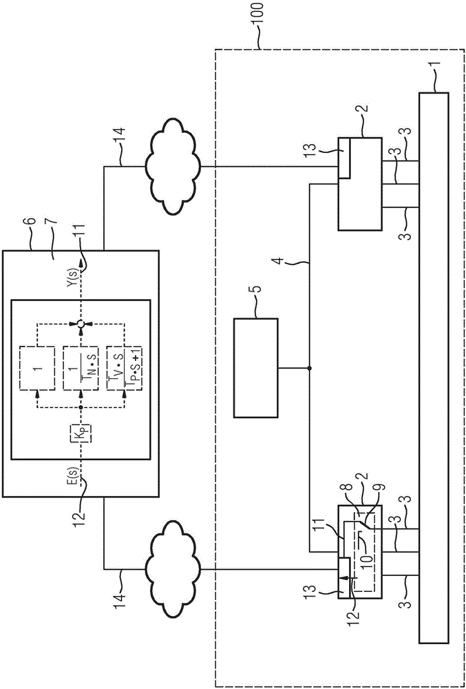
[0017] figure 1 A system 100 is shown for controlling an industrial process 1 , for example a process for water treatment in a purification plant or a process for conveying liquids or gases through pipelines. The process 1 is controlled and regulated via a decentralized plant-side automation unit 2 which for this purpose has an on-site connection to the process. figure 1 A series of operative connections 3 of sensors and actuators not shown in detail. Two automation units 2 are shown by way of example, in reality there are many more which control, regulate and monitor the process. The automation unit 2 is connected via a first data connection 4 to a monitoring system 5 which controls and monitors the process 1 . The automation unit 2 performs monitoring and regulating functions 8 acting on the process. In this configuration, the system 100 is efficient and able to fulfill its control, regulation and monitoring tasks. The system 100 is expanded by a computing unit 6 outside...


PUM


Abstract

A system (100) for controlling a process (1) having at least one automation unit (2) on the plant side that calculates a plurality of first process variables (10) and influences the process and is connected by first data link (4) to a monitoring system (5) that controls and / or monitors the process. The system has an external computing unit (6) that is connected by a distributed communication mechanism to the automation unit (2) and exchanges data with it using a second data link (14). The external computing unit calculates a plurality of second process variables (11) that the of the automation unit uses to influence the process. A method for extending the function of at least one plant-side automation unit is also disclosed.

Description

technical field [0001] The invention relates to a control system for distributed process control of technical installations and a method for controlling technical installations. Background technique [0002] Often, several devices for process control perform simple automation and control-technical tasks. These tasks are often not time-critical with controlled variables in the range of seconds. Examples here are water treatment in sewage treatment plants, further examples are pipeline management for various pipeline systems (gas, oil, water), drying of semi-finished products in the food industry (edible oil drying, grain drying) or Manufacturing of glass, dragging of single crystals or general flotation. Usually these plants also consist of a plurality of mainly also spatially separated smaller automation units, which then leads to the fact that the individual process tasks are also carried out in a distributed manner. Due to their limited computing power, such smaller aut...

Claims


Application Information

Patent Timeline
Patent Type & Authority Applications(China)
IPC IPC(8): G05B19/418
CPCG05B19/41865G05B2219/32252G05B19/4185G05B2219/32136Y02P90/02G06F30/20G05B11/011G05B19/41835G05B19/41885G05B2219/13179G05B2219/13186G05B2219/33317
Inventor 克里斯蒂安·黑克赫里特·沃尔夫
Owner SIEMENS AG
Learn More