Dual clutch lock cylinder device

A dual-clutch, lock cylinder technology, applied in building locks, non-mechanical transmission-operated locks, buildings, etc., can solve the problems of lack of emergency door opening function of mechanical lock cylinders, difficult maintenance, complicated mechanism, etc., to achieve clear industrial division of labor, Effects of cost reduction and emphasis on safety

Inactive Publication Date: 2018-09-25
詹万泉
View PDF6 Cites 0 Cited by
  • Summary
  • Abstract
  • Description
  • Claims
  • Application Information

AI Technical Summary

Problems solved by technology

The internal clutch of the lock cylinder is to transform the mechanical structure of the lock cylinder. The outer handle connecting rod penetrates the hole of the lock cylinder and the clutch mechanism in the inner protective cover is used for clutching. The original mechanical lock cylinder must be replaced with a customized mechanical lock cylinder. The position of the mechanical lock cylinder, the internal clutch of the lock cylinder lacks an important emergency door opening function of the mechanical lock cylinder; the common advantage of the internal clutch is that the clutch mechanism is in the protective cover inside the door, which has high safety; the disadvantage is that the mechanism is complicated and takes up a lot of space , the cost is high, the clutch in the lock body needs to be replaced with a lock body, the clutch in the lock cylinder lacks the emergency opening function of the mechanical lock cylinder, and it is difficult to maintain in case of failure

Method used


Image

  • Dual clutch lock cylinder device
  • Dual clutch lock cylinder device
  • Dual clutch lock cylinder device

Examples


Embodiment Construction

[0047] In order to make the purpose, technical solutions and advantages of the embodiments of the present invention clearer, the technical solutions in the embodiments of the present invention will be clearly and completely described below in conjunction with the drawings in the embodiments of the present invention. Obviously, the described embodiments It is a part of embodiments of the present invention, but not all embodiments. Based on the embodiments of the present invention, all other embodiments obtained by persons of ordinary skill in the art without making creative efforts belong to the protection scope of the present invention.

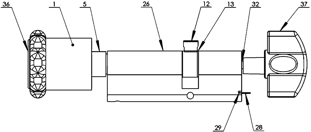
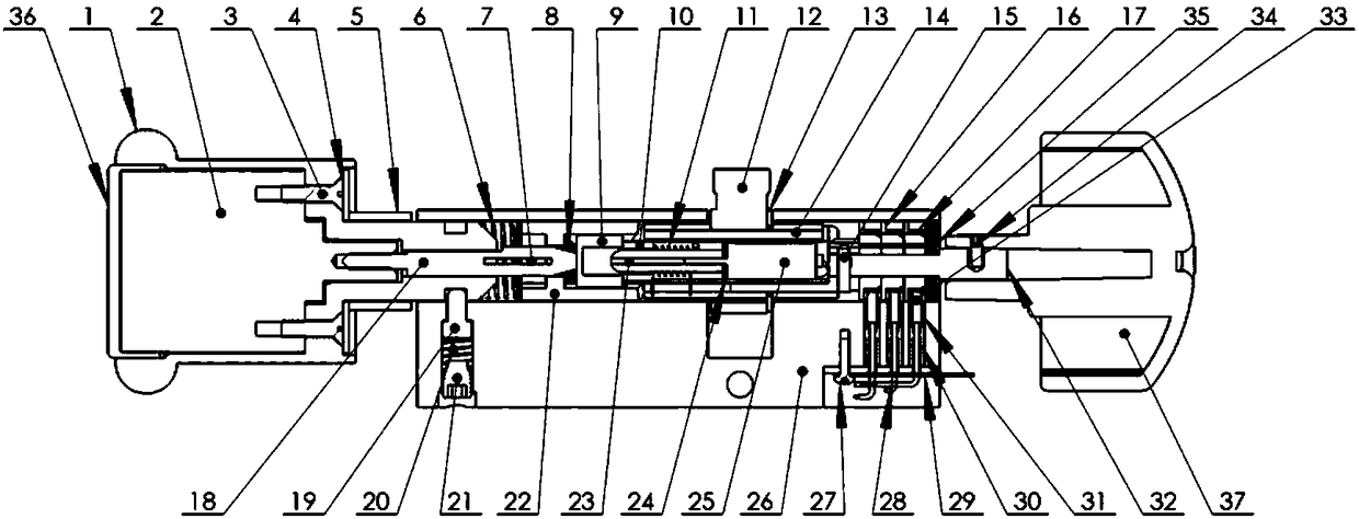
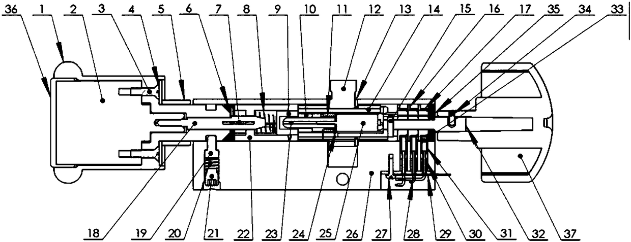
[0048] Such as figure 1 with 2 As shown, this embodiment provides a dual-clutch lock cylinder device, including an outer handle (1), a mechanical lock cylinder (2), a mechanical lock cylinder fixing screw (3), an anti-demolition steel sheet (4), and an anti-saw steel sleeve (5), locking sleeve compression spring (6), over-force protection s...


PUM


Abstract

The invention discloses a double-clutch lock cylinder device which comprises an outer handle, a mechanical lock cylinder, a mechanical lock cylinder fixing screw, a demounting-preventing steel sheet, an anti-sawing steel sleeve, a locking sleeve compression spring, an excessive-force protection steel sheet, an unlocking sleeve compression spring, an unlocking sleeve, a transmission sliding sleeve, a motor transmission spring, a lock cylinder shifting fork, a sleeve clamping spring, a lock cylinder sleeve, an inner transmission shaft fixing pin, a collecting ring support, a collecting ring, an outer transmission shaft, a movable pin, a movable pin supporting spring, a movable pin fixing screw plug, a locking sleeve, a motor transmission worm, a motor transmission position induction plate, a motor, a lock cylinder support, a collecting brush fixing screw, an electric brush wire, a collecting brush fixing plate, a contact compression spring, a contact insulation protection sleeve, an inner transmission shaft, an electric brush contact, an inner handle fixing screw, an inner transmission shaft supporting block piece, a mechanical lock cylinder protection cover and an inner handle. No door or lock or panel needs to be replaced, operation is easy, double clutches coexist in the electronic mechanical lock cylinder, safety and convenience are paid attention to, and meanwhile the installation and maintenance cost is reduced.

Description

technical field [0001] The invention relates to an anti-theft safety lock cylinder, in particular to a lock cylinder device integrated with electronic and mechanical dual clutch functions. Background technique [0002] The mechanical lock cylinder on the market is a purely mechanical pin-engagement and separation mechanism that only relies on the arrangement of keyhole pins or blades. [0003] Due to the common requirements of safety and convenience, more and more people now hope to upgrade the original mechanical anti-theft locks to electronic anti-theft locks. However, due to the diversity of the original mechanical lock body structure, the replacement work has become quite difficult. In addition, the anti-theft lock is a precise component, and a slight deviation in the size of the replacement part will bring great trouble to the installation and future use. Most of the electronic anti-theft lock products currently occupying a dominant position in the market can only repl...

Claims


Application Information

Patent Timeline
Patent Type & Authority Patents(China)
IPC IPC(8): E05B47/00
CPCE05B47/0012E05B2047/0091
Inventor 詹万泉
Owner 詹万泉
Why Eureka
Try Eureka