Mechanism for punching side wall of firefighting main machine shell

A technology for the side wall of the shell and the fire-fighting main engine, which is applied in the direction of the feeding device, manufacturing tool, positioning device, etc., can solve the problems of low punching efficiency, punching error, troublesome fixing, etc., and achieve accurate punching, high efficiency, Firm clamping effect

Inactive Publication Date: 2016-12-14
绍兴柯桥远达纺织有限公司
View PDF7 Cites 13 Cited by
  • Summary
  • Abstract
  • Description
  • Claims
  • Application Information

AI Technical Summary

Problems solved by technology

[0002] At present, the existing fire-fighting control host shells need to be punched and formed on the side walls to form ventilation holes before use. However, the existing control host shells are usually manually fixed on the frame when punching holes. On the other hand, the fixation is troublesome and the effect is not ideal, resulting in errors when punching, resulting in low punching efficiency

Method used


Image

  • Mechanism for punching side wall of firefighting main machine shell
  • Mechanism for punching side wall of firefighting main machine shell
  • Mechanism for punching side wall of firefighting main machine shell

Examples


Embodiment Construction

[0021] The specific implementation manners of the present invention will be further described in detail below in conjunction with the accompanying drawings and embodiments. The following examples are used to illustrate the present invention, but are not intended to limit the scope of the present invention.

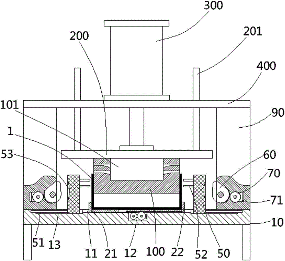
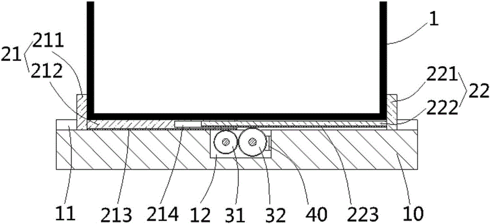
[0022] see figure 1 , figure 2 , a kind of mechanism that is used for punching the side wall of fire main engine housing described in the present invention, comprises frame 10, and the middle part of the top surface of described frame is formed with slot 11, and described slot is inserted and sleeved with The first clamping plate 21 and the second clamping plate 22 that are both “L” shaped and oppositely arranged, and the first clamping plate 21 and the second clamping plate 22 are respectively connected to the two sides of the shell 1 to be processed. Correspondingly, the first clamping plate 21 includes a first vertical plate 211 and a first horizontal plate 212 perpe...


PUM


Abstract

The invention discloses a mechanism for punching the side wall of a firefighting main machine shell. The mechanism comprises a rack; an inserting groove is formed in the middle of the top surface of the rack; a first clamping plate and a second clamping plate which are both in L shapes and are arranged oppositely are inserted into the inserting groove in a sleeved mode and correspond to the edge parts of the two sides of a to-be-machined shell correspondingly; slide grooves are formed in the positions, on the two sides of the inserting groove, of the top surface of the rack; punching plates are inserted in the slide grooves in a sleeved mode; punching heads are formed in the positions, facing the upper end of the side wall of the to-be-machine shell, of the punching plates; impact cams are arranged on the side, back onto the punching heads, of the punching plates; transmission gear rings are formed in the arc-shaped walls, opposite to convex parts, of the impact cams and are connected with rotary gears in an engaged mode; a middle supporting block is inserted into the to-be-machined shell in a sleeved mode; a blanking groove is formed in the middle of the middle supporting block; and impact through holes corresponding to the punching heads of the punching plates are formed in the left side wall and the right side wall of the blanking groove. By means of the mechanism, the firefighting main machine shell can be firmly clamped and fixed, and the punching efficiency is high.

Description

Technical field: [0001] The invention relates to the technical field of fire-fighting equipment, in particular to a mechanism for punching holes on the side wall of a fire-fighting host casing. Background technique: [0002] At present, the existing fire-fighting control host shells need to be punched and formed on the side walls to form ventilation holes before use. However, the existing control host shells are usually manually fixed on the frame when punching holes. On the other hand, the fixation is troublesome and the effect is not ideal, resulting in errors when punching, resulting in low punching efficiency. Invention content: [0003] The object of the present invention is to solve the problems existing in the prior art, and to provide a mechanism for punching the side wall of the fire main engine shell which firmly clamps and fixes the fire main engine shell and has high punching efficiency. [0004] The invention relates to a mechanism for punching holes on the s...

Claims


Application Information

Patent Timeline
IPC IPC(8): B21D28/24B21D43/00
CPCB21D28/24B21D43/003
Inventor 李风浪李舒歆
Owner 绍兴柯桥远达纺织有限公司
Why Eureka
Try Eureka