
Self-adaption valley value current type pulse sequence control method and device thereof

A technology of valley current and pulse sequence, which is applied in the field of adaptive valley current pulse sequence control method and its device, can solve the problems of increasing the complexity and cost of the control circuit, avoid the valley oscillation of the inductor current, and simplify the control Circuit, the effect of extending the power range

Inactive Publication Date: 2016-12-07
CHINA UNIV OF MINING & TECH
View PDF5 Cites 0 Cited by
  • Summary
  • Abstract
  • Description
  • Claims
  • Application Information

AI Technical Summary

Problems solved by technology

A multi-valley current-mode pulse sequence (MVC-PT) control is proposed to address the defects of VCM-PT control, which broadens the power range of the converter under valley-value current mode control, but as the power range increases, a large number of load current references need to be preset value and the valley value of the inductor current, thus increasing the complexity and cost of the control circuit

Method used


Image

  • Self-adaption valley value current type pulse sequence control method and device thereof
  • Self-adaption valley value current type pulse sequence control method and device thereof
  • Self-adaption valley value current type pulse sequence control method and device thereof

Examples


Embodiment 1

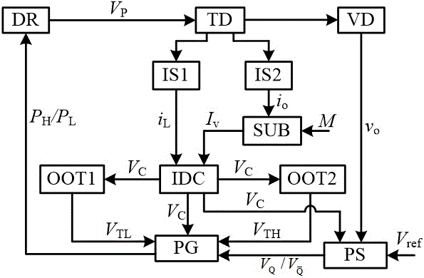
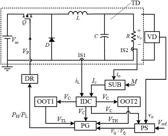
[0040] figure 1 It is shown that a specific embodiment of the present invention is a control method of a switching converter, and its specific method is:

[0041] The pulse selection rule is: at the beginning of each switching cycle, if the output voltage v o less than the reference voltage V ref , using a high power pulse P H Control the switching tube Q in the converter; otherwise, use low power pulse P L Control switch tube Q.

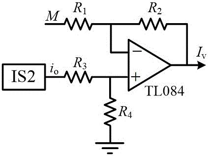
[0042] The rule for determining the valley value of the inductor current is: at the end of each switching cycle, the load current i o The difference from the preset current value M is taken as the inductor current valley value I of the switching cycle v .

[0043] The circuit consists of a converter TD and a controller. The controller includes a voltage detection circuit VD, an inductor current detection circuit IS1, a load current detection circuit IS2, a subtraction circuit SUB, a comparison circuit IDC, a pulse selector PS, a pulse generato...

Embodiment 2

[0057] Figure 10 It is shown that this example is basically the same as the first example, except that the switching converter TD controlled in this example is a Boost converter.

Embodiment 3

[0059] Figure 11 It is shown that this example is basically the same as the first example, except that the switching converter TD controlled in this example is a Buck-Boost converter.

[0060] The inventive method can be realized with analog device or digital device conveniently; Except the switching converter in the above embodiment, also can be used for Cuk converter, flyback converter, forward converter, half-bridge converter, A switching converter composed of various power circuits such as a full bridge converter.

[0061] Embodiment 1 of the present invention adopts the circuit parameters in Table 1 for simulation.

[0062] Table 1 Converter simulation parameters

[0063] name


PUM


Abstract

The invention discloses a self-adaption valley value current type pulse sequence control method for a continuous conductive mode switch convertor and a device of the method. At the starting time of each switching period, effective control pulse in the switching period is selected according to a relation between output voltage vo and reference voltage Vref; at the ending time of each switching period, the difference between a load current Io and a preset current value M serves as an inductive current valley value Iv of the switching period. By means of the method, the power range of the converter is greatly expanded, the structure of the device is simple, the dynamic performance is good, and the self-adaption valley value current type pulse sequence control method and the device are suitable for switch converters of various topological structures.

Description

technical field [0001] The invention relates to a switching converter, in particular to an adaptive valley value current type pulse sequence control method and a device thereof. Background technique: [0002] With the development of power electronics technology and the popularization of portable electronic devices, a novel nonlinear non-linear Discrete Control Method—Pulse Train (PT) Control. The adjustment of the output voltage is realized by adjusting the preset combination of high and low power pulse sequences with the same frequency but different duty ratios. It has the characteristics of simple circuit implementation, fast dynamic response and strong robustness, and is suitable for reliability. A switching power supply system with high requirements. [0003] PT control has been successfully applied in switching converters with inductor current discontinuous conduction mode (DCM), that is, the output voltage increases when high power pulses are applied, and the output ...

Claims


Application Information

Patent Timeline
Patent Type & Authority Applications(China)
IPC IPC(8): H02M3/155
CPCH02M3/155H02M1/0003
Inventor 于东升王龙朱旺耿乙森杨杰叶宗彬马草原
Owner CHINA UNIV OF MINING & TECH
Learn More