Driving method and driving deice for display panel

A technology of display panel and driving method, applied in static indicator, data processing input/output process, instrument, etc., can solve the problems of source signal delay, dim brightness, leakage, etc., and achieve improved signal distortion and consistent display brightness , Improve the effect of experience

Active Publication Date: 2016-12-07
WUHAN CHINA STAR OPTOELECTRONICS TECH CO LTD
View PDF4 Cites 5 Cited by
  • Summary
  • Abstract
  • Description
  • Claims
  • Application Information

AI Technical Summary

Problems solved by technology

[0004] However, when some display units, such as N rows of pixels, stop to scan some touch units after scanning, the source signal (Source) of the data line driving the display panel will always be kept at the ground (GND) level. flat low state, which will cause leakage
At this time, when part of the touch units are scanned, and then scan the next row of pixels arranged in sequence, such as the N+1 row of pixels, the Source signal of the N+1th row of pixels will be distorted due to electric leakage ( like figure 2 As shown), that is, there is a serious delay (Delay) phenomenon on the rising and falling edges of the Source signal, which eventually leads to the fact that the pixels in the N+1th row cannot be fully filled, and it appears as the N+1th row on the display. The brightness of the pixels in the row is darker, forming a dark line (such as image 3 shown), which greatly reduces the user experience

Method used


Image

  • Driving method and driving deice for display panel
  • Driving method and driving deice for display panel
  • Driving method and driving deice for display panel

Examples


Embodiment Construction

[0024] The present invention will be described in detail below in conjunction with the accompanying drawings and embodiments.

[0025] Figure 4 It is a flow chart of the driving method of the display panel according to the first embodiment of the present invention. Such as Figure 4 As shown, the method includes the steps of:

[0026] Step S101: Detect the working state of the display panel.

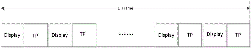
[0027] In step S101, the working state of the display panel includes a display state and a touch scanning state. Wherein, during the display period of one frame of image, the working state of the display panel is switched back and forth between the display state and the touch scanning state.

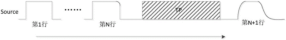
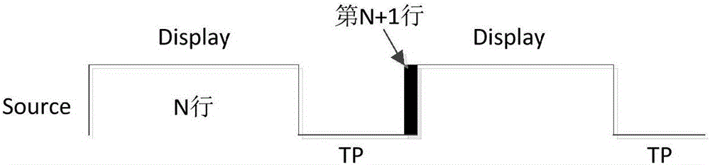
[0028] Step S102: switch the bias current in the data line driving circuit according to the working state of the display panel, so as to make the display brightness of the display panel consistent.

[0029] In step S102, in the driving structure of the small and medium-sized display panel, th...


PUM


Abstract

The invention discloses a driving method and a driving deice for a display panel. The driving method comprises steps of detecting the working state of the display panel and switching bias current in a data line driving circuit according to the working state of the display panel. By the above mode, the invention solves the problem that grid signals added on a data line are distorted due to electric leakage, enables the display brightness of the display panel to be consistent, and further improves the user experience.

Description

technical field [0001] The invention relates to the field of liquid crystal display, in particular to a driving method and a driving device of a display panel. Background technique [0002] With the rapid advancement of technology, people have higher and higher requirements for the performance and appearance of consumer electronics products, especially smart phones and tablet computers. Lightness, thinness, shortness, and smallness have become common interests pursued by major electronic product manufacturers in order to cater to the market. In order to realize thinner and lighter electronic products, most of the screens used in mobile phones and tablet computers are capacitive touch screens that integrate display and touch functions, including three types: On-Cell, Hybrid In-Cell and Full In-Cell , and the latter can make the display screen thinner and lighter than the previous two technologies. [0003] The small and medium-sized LTPS LCDs of the Full In-Cell architectur...

Claims


Application Information

Patent Timeline
Patent Type & Authority Applications(China)
IPC IPC(8): G09G3/36G06F3/041
CPCG06F3/0416G09G3/36G09G3/3685G09G2320/0233G06F3/0412G06F3/04184G06F3/044G09G3/3648G09G2310/08G09G2330/12
Inventor 李曼陈伟
Owner WUHAN CHINA STAR OPTOELECTRONICS TECH CO LTD
Why Eureka
Try Eureka