
Pressure induction touch screen and display device

A technology for sensing touch and pressure, applied in the field of pressure-sensitive touch screens and display devices, can solve the problems of reducing pressure deformation, reducing the accuracy of pressure touch, and increasing the thickness of the display panel, reducing size and avoiding temperature unevenness. Effect

Active Publication Date: 2016-12-07
SHANGHAI TIANMA MICRO ELECTRONICS CO LTD +1
View PDF4 Cites 7 Cited by
  • Summary
  • Abstract
  • Description
  • Claims
  • Application Information

AI Technical Summary

Problems solved by technology

The pressure touch integrated in the touch screen cannot be used due to thickness and display problems
When the strain gauge is placed under the backlight layer of the display panel, the thickness of the entire display panel will be increased, which is not conducive to the thinning of the display panel. At the same time, since the strain gauge is placed under the backlight layer, the sensitivity of finger touch will be greatly weakened , reduce touch sensitivity
When the strain gauge is arranged around the frame of the display panel, since the frame of the display panel is mainly attached by double-sided tape, there will inevitably be a gap between the double-sided tape and the display panel, which will greatly reduce the pressure caused by the pressure applied to the surface of the display panel. Deformation, which reduces the precision of Force Touch

Method used


Image

  • Pressure induction touch screen and display device
  • Pressure induction touch screen and display device
  • Pressure induction touch screen and display device

Examples


Embodiment Construction

[0036] A pressure-sensitive touch screen and display device of the present invention will be described in more detail below in conjunction with schematic diagrams, wherein a preferred embodiment of the present invention is shown, and it should be understood that those skilled in the art can modify the present invention described here and still implement the present invention beneficial effect. Therefore, the following description should be understood as the broad knowledge of those skilled in the art, but not as a limitation of the present invention.

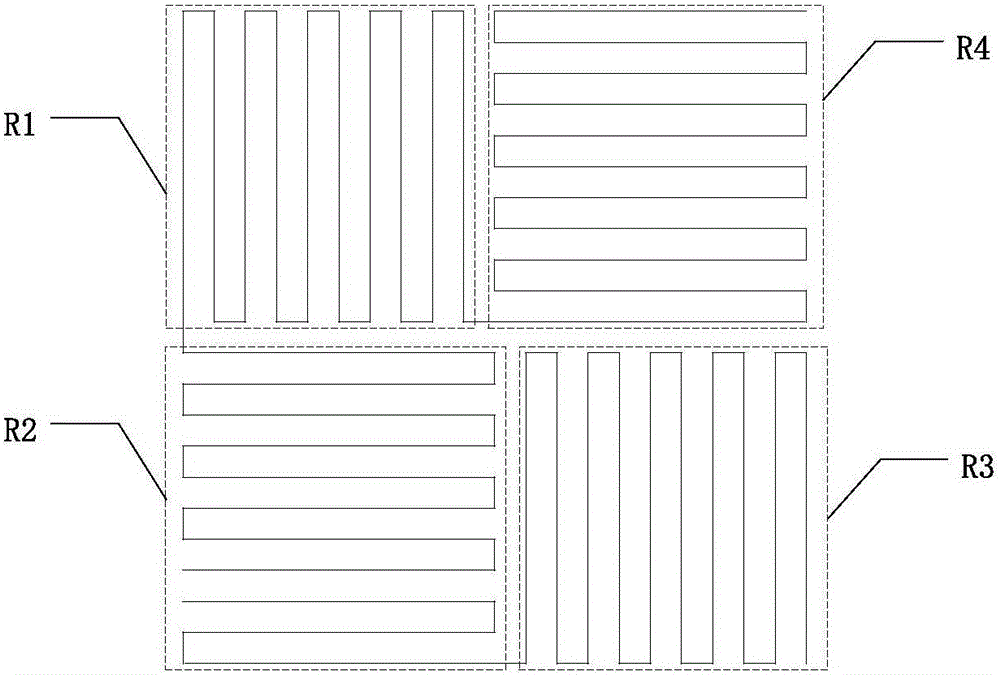
[0037] figure 1 It is a schematic diagram of a pressure sensing module in the prior art, and the pressure sensing in the prior art mostly uses a Wheatstone bridge to realize pressure detection. In the display screen, a Wheatstone bridge is formed with 4 resistors as a unit. The first resistor R1, the second resistor R2, the third resistor R3 and the fourth resistor R4 are composed of strained materials, wherein the strain dire...


PUM


Abstract

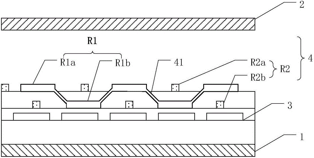
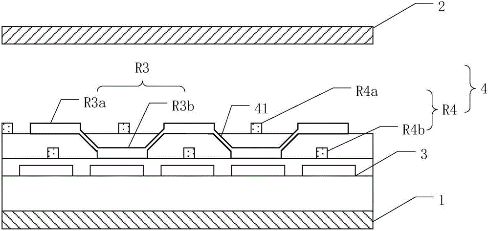
The invention provides a pressure induction touch screen and a display device. The screen comprises a first substrate and a second substrate, a pixel arranged on the first substrate, and at least one group of pressure induction modules comprising a first pressure induction group and a second pressure induction group. The first pressure induction group comprises a first part and a second part. The first part of the first pressure induction group and the second part of the first pressure induction group are located in different layers. The second pressure induction group comprises a first part and a second part. The first part of the second pressure induction group and the second part of the second pressure induction group are overlapped with each other partially. The second part of the first pressure induction group and the first part of the second pressure induction group are overlapped with each other partially. The second part of the first pressure induction group is overlapped with the first part of the second pressure induction group partially. The pressure induction touch screen and the display device effectively solve differentiation problems brought by two layers of metal due to technology.

Description

technical field [0001] The invention relates to the field of display technology, in particular to a pressure-sensitive touch screen and a display device. Background technique [0002] At present, as an interactive medium, the touch screen is the most convenient, fast and natural human-computer interactive medium. In the prior art, most touch screens are self-capacitance or mutual-capacity. [0003] The touch principle of the self-capacitive touch screen is mainly that the common electrodes are multiplexed as touch electrodes, and the touch electrodes are arranged in an array, and the touch electrodes are both driving electrodes and sensing electrodes. When a finger touches the touch electrode, the corresponding touch electrode forms a capacitance with the finger, and the signal changes due to the capacitance. The driver IC senses the physical position of the touch by receiving the sensing signal on the touch electrode. [0004] The touch principle of the mutual capacitive ...

Claims


Application Information

Patent Timeline
Patent Type & Authority Applications(China)
IPC IPC(8): G06F3/041
CPCG06F3/0414G06F2203/04103
Inventor 李谷骏刘亮杜凌霄慎言
Owner SHANGHAI TIANMA MICRO ELECTRONICS CO LTD
Learn More