
Autofocus head mounted display device

A head-mounted display and auto-focus technology, applied in installation, optics, instruments, etc., can solve the problem of only imaging at a fixed distance, and achieve the effects of increasing diversity, improving comfort, and increasing popularity

Inactive Publication Date: 2016-12-07
SHINYOPTICS +1
View PDF3 Cites 35 Cited by
  • Summary
  • Abstract
  • Description
  • Claims
  • Application Information

AI Technical Summary

Problems solved by technology

[0005] In view of the above-mentioned problems in the prior art, the purpose of the embodiments of the present invention is to provide an auto-focusing head-mounted display device to solve the problem that the existing head-mounted display device can only image images at a fixed distance when displaying images. question

Method used


Image

  • Autofocus head mounted display device
  • Autofocus head mounted display device
  • Autofocus head mounted display device

Examples


Embodiment Construction

[0058] In order to facilitate the understanding of the technical features, content and advantages of the present invention and the effects that can be achieved, the present invention will be described in detail as follows in conjunction with the accompanying drawings, and the expressions of the embodiments are as follows. The purpose of illustration and auxiliary instructions is not necessarily the true proportion and precise configuration of the present invention after implementation, so the scale and configuration relationship of the attached drawings should not be interpreted or limited to the scope of protection of the present invention in actual implementation. bright.

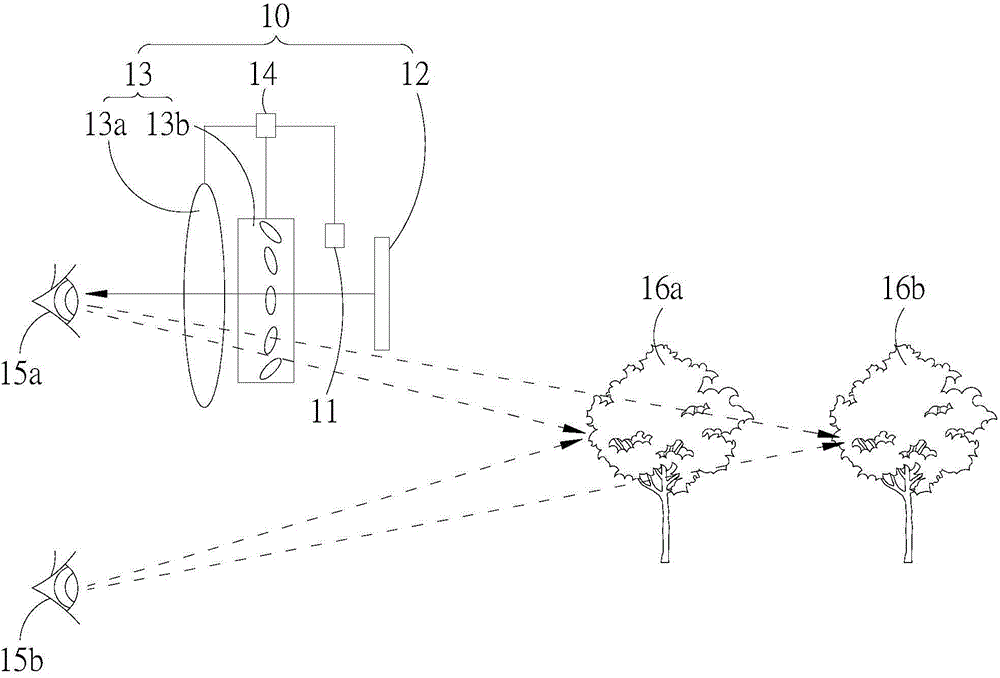
[0059] see figure 1 , which is a schematic diagram of the auto-focusing head-mounted display device of the present invention. In the figure, the auto-focusing head-mounted display device includes a first imager 10 and an eye tracker 11 . The first imager 10 includes a first display element 12, a first o...


PUM


Abstract

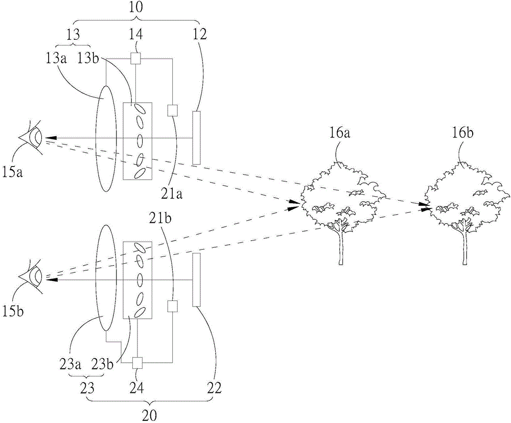
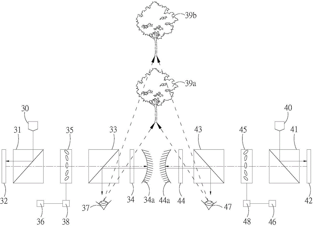
Autofocus head mounted display device, including an imager (10) and an eyeball tracker (11). The imager includes a display element (12, 32, 52), an optical element (13, 35, 55) and a controller (14, 38, 58). An image light is projected to one of the eyeballs (15a, 15b, 37, 47, 57) of the user by the display element. The convergence or divergence of the image light is adjusted by the optical element through the controller. The image is presented at an imaging position in front of the eyeballs of the user. The eyeball tracker is disposed at the position in front of the user's eyes. Both left eye and right eye rotational angles are detected simultaneously, so as to determine a focus position of the user's eyes. The eyeball tracker is connected to the controller. The optical element is adjusted by comparing the imaging position and the focus position, and the imaging position of the image is moved to the focus position, thus preventing the user from having eye fatigue caused by long-term focus in the same position, and enhancing user of comfortableness.

Description

technical field [0001] The present invention relates to an auto-focusing head-mounted display device, in particular to a head-mounted display device with an eye tracker that automatically adjusts the imaging position by detecting the focus positions of both eyes. Background technique [0002] In recent years, with the continuous development of head-mounted display devices, the head-mounted display device can match the displayed image with the helmet or glasses worn on the user's head, and project it onto the display screen of the head-mounted device to form an image visible to the user , due to being close to the user's eyeballs, these images will be able to achieve a wide visual effect with a small display area, allowing the user to use the head-mounted display device to see the image to be presented. [0003] Furthermore, the head-mounted display device can form virtual images in front of the user's eyes by using the arrangement of optical elements, and these images, wheth...

Claims


Application Information

Patent Timeline
Patent Type & Authority Applications(China)
IPC IPC(8): G02B27/01G02B7/28
CPCG02B2027/0185G02B2027/0187G02B5/30G02B27/017G02B2027/0127G02B27/0172G02B2027/0138G02B27/0093G02B7/28G02B2027/0132
Inventor 陈燕晟游进洲陈俊民廖政顺陈松楠
Owner SHINYOPTICS
Learn More