
Adjustable flexible vibration test bench

A vibration test bench, adjustable technology, applied in vibration testing, testing of machine/structural components, measuring devices, etc., can solve problems such as damage to support guide column components, intense movement, damage to bushing cages, etc., to achieve extended use Lifespan, guarantee strength and effect, effect of easy replacement

Inactive Publication Date: 2016-12-07
张泓泽
View PDF0 Cites 3 Cited by
  • Summary
  • Abstract
  • Description
  • Claims
  • Application Information

AI Technical Summary

Problems solved by technology

[0004] During the working process of the traditional vibration test bench, the supporting guide column assembly of the vibration test bench is the main force-bearing part and the movement is relatively intense. It can be used for a long time in a clean environment and without lateral force, but in some harsh environments For example, when testing the vibration of a car, due to the high-speed vibration of the vibration test bench and the heavy weight of the car, the support guide column assembly receives a large lateral force, and long-term use will cause damage to the support guide post assembly; secondly, sand and other debris After the swarf falls into the bushing and retainer, under the condition of large lateral force, it will quickly cause damage to the bushing and retaining frame, resulting in the scrapping of the supporting guide post assembly, so the life of the supporting guide post assembly of the vibration test bench is longer short

Method used


Image

  • Adjustable flexible vibration test bench

Examples


Embodiment Construction

[0016] The following will clearly and completely describe the technical solutions in the embodiments of the present invention with reference to the accompanying drawings in the embodiments of the present invention. Obviously, the described embodiments are only some of the embodiments of the present invention, not all of them. Based on the embodiments of the present invention, all other embodiments obtained by persons of ordinary skill in the art without making creative efforts belong to the protection scope of the present invention.

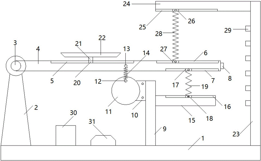
[0017] see figure 1 , the present invention provides a technical solution: including a base 1, the left upper surface of the base 1 is vertically connected with a rotating shaft support 2, a rotating shaft 3 is installed on the top of the rotating shaft support 2, and the rotating shaft support 2 A rocker arm 4 is hinged through a rotating shaft 3, a first chute 5 is arranged in the middle of the upper surface of the rocker arm 4, and a second ch...


PUM


Abstract

The invention discloses an adjustable flexible vibration test bench, and the test bench comprises a pedestal. The upper surface of the left side of the pedestal is vertically connected with a rotating shaft support seat, and the top of the rotating shaft support seat is provided with a rotating shaft. The rotating shaft support seat is hinged to a rocking arm through the rotating shaft, and the central part of the upper surface of the rocking arm is provided with a first chute. The right side of the upper surface of the rocking arm is provided with a second chute, and the right side of the lower surface of the rocking arm is provided with a third chute. The central part of one end of the rocking arm is provided with a speed sensor. The first chute on the rocking arm cooperates with a horizontal sliding block, so the test bench can adjust the distance from the horizontal sliding block to the rotating shaft conveniently, changes the amplitude side, and employs the rotation of a rotating disc and the elastic force of a first tension spring as the power of the vertical vibration of the rocking arm. The first tension spring is convenient to replace, thereby guaranteeing the vibration intensity and effect, and prolonging the service life. The test bench effectively adjusts the amplitude and frequency of the rocking arm through the combination of a second tension spring and a third tension spring.

Description

technical field [0001] The invention relates to the technical field of vibration test equipment, in particular to an adjustable flexible vibration test bench. Background technique [0002] The vibration test bench can simulate the vibration environment of some products during transportation, and is used to test the shock resistance, reliability and integrity of product structures such as automobiles, toys, furniture, and packaging. [0003] A traditional vibration test bench consists of a frame, a power unit, a cam, a roller, a support guide column assembly, and a vibration platform. The support guide post assembly includes a support guide post, a bushing retainer and a support guide bushing. Needle rollers or balls are installed on the bushing holder, and the bushing holder is located between the support guide post and the support guide sleeve, so that the friction force between the support guide post and the support guide sleeve is small and has a guiding effect, and the ...

Claims


Application Information

Patent Timeline
Patent Type & Authority Applications(China)
IPC IPC(8): G01M7/04
CPCG01M7/04
Inventor 张泓泽刘之琪
Owner 张泓泽
Learn More