
floor monitor stand

A monitor stand, floor-standing technology, applied in the direction of machine/stand, supporting machine, mechanical equipment, etc., can solve the problems of easy wear and failure, inconvenient adjustment, etc., and achieve the effect of beautiful appearance, convenient assembly and adjustment, and small size

Active Publication Date: 2019-11-01
KUNSHAN HONGJIE ELECTRONICS CO LTD
View PDF6 Cites 1 Cited by
  • Summary
  • Abstract
  • Description
  • Claims
  • Application Information

AI Technical Summary

Problems solved by technology

[0005] The third method is to adjust the height of the TV through the friction locking structure of the hanging board and the column. This is similar to the first method, but it is also inconvenient to adjust, requires the cooperation of multiple people, and is prone to wear and tear.

Method used


Image

  • floor monitor stand
  • floor monitor stand
  • floor monitor stand

Examples


Embodiment

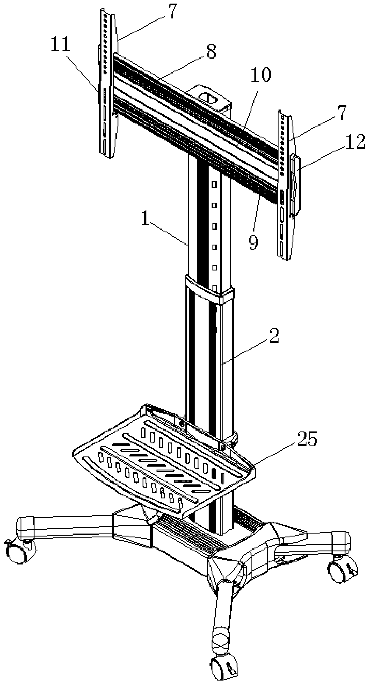
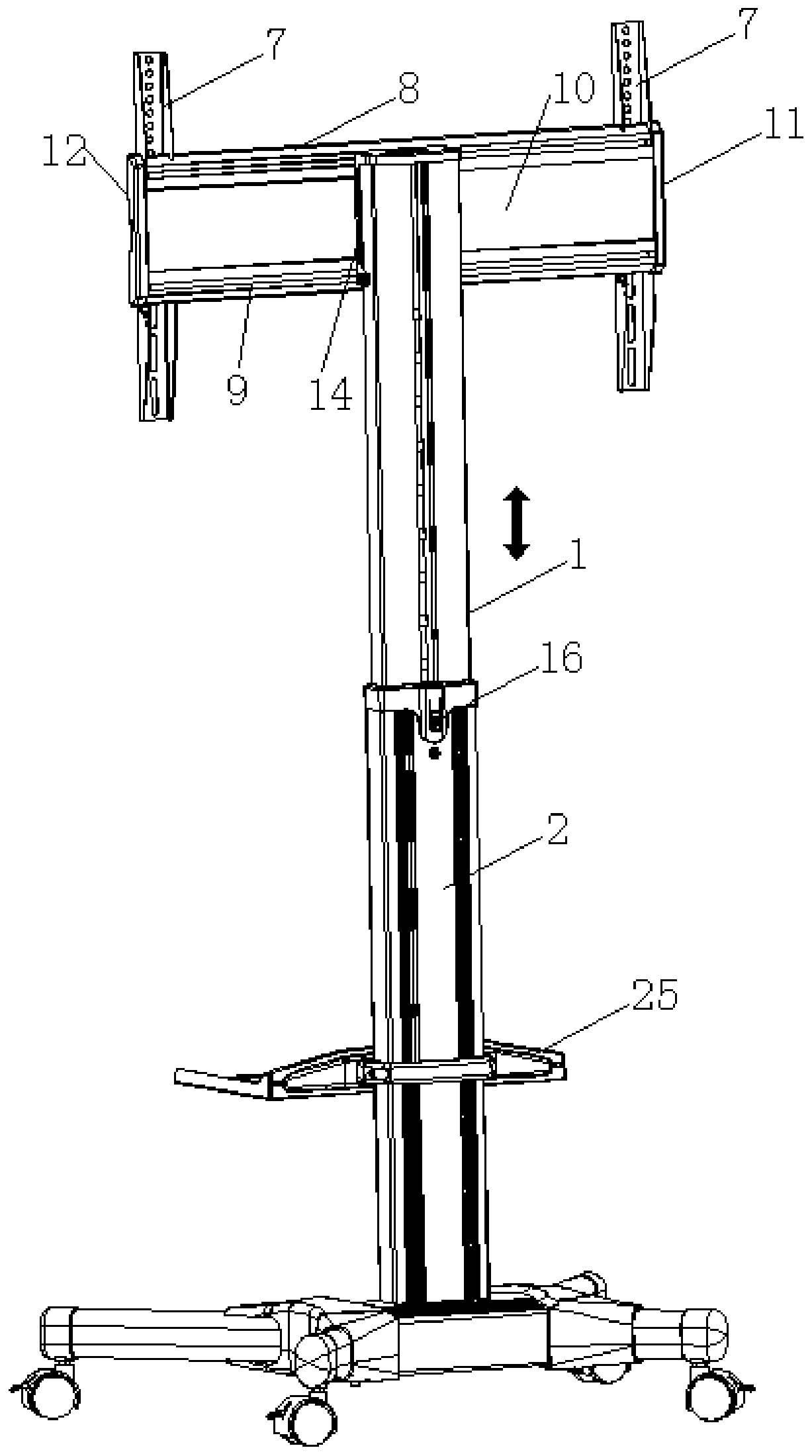
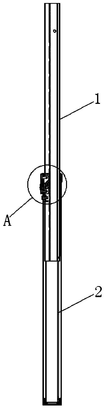
[0032] Embodiment: A floor-standing display stand, including a column part, a base part and a TV installation part, wherein:

[0033] The column part includes an upper column 1, a lower column 2, a clip 3 and an elastic member 4. Based on the actual use direction, the axial direction of the upper and lower columns 2 is the longitudinal direction, and the upper column 1 can be slidably inserted in the lower column vertically. In the column 2, a number of longitudinally arranged sockets 5 are arranged at intervals on the side wall of the upper column 1, and the clip 3 is installed on the lower column 2 so as to be able to rotate around the horizontal axis 6. One end of the clip 3 forms a ratchet wheel tooth structure, The ratchet tooth structure can just extend into the socket 5 on the side wall of the upper column 1, and the ratchet tooth structure of the clamp 3 only allows the upper column 1 to slide upwards, and the elastic member 4 can provide one end of the clamp 3 to exten...


PUM


Abstract

The invention discloses a floor type displayer support. A stand column portion comprises an upper stand column, a lower stand column, a clamping part and an elastic part. The axial direction of the upper stand column and the lower stand column is the longitudinal direction. The upper stand column is inserted in the lower stand column in a longitudinally slidable mode. The side wall of the upper stand column is provided with a plurality of sockets arranged in the longitudinal direction at intervals. The clamping part is installed on the lower stand column and can rotate around the horizontal axis. A ratchet wheel tooth structure is formed at one end of the clamping part and can just extend into the sockets in the side wall of the upper stand column, and the ratchet wheel tooth structure of the clamping part only allows the upper stand column to slide upwards. The elastic part can apply set retention force to one end of the clamping part so as to make the end of the clamping part extend into the sockets in the side wall of the upper stand column. The side wall of the lower stand column is further provided with a driving mechanism which can drive the clamping part to rotate so as to make one end of the clamping part retreat out of the sockets of the upper stand column. The lower end of the lower stand column is fixedly connected with a base portion. A television mounting portion is fixedly connected with the upper stand column. According to the floor type displayer support, the height of a television is convenient to adjust, the packaging size is small, storage and transportation are convenient, and the appearance is attractive.

Description

technical field [0001] The invention relates to a TV bracket, in particular to a floor-standing monitor bracket. Background technique [0002] At present, the large living room, meeting room, public place, etc. of the family need to use floor-standing TV stands. Conventional floor-standing TV stands are all integrated steel plate bases. The bases are generally equipped with universal wheels for supporting and moving positions. The connecting plate used for TV installation is generally a sheet metal stamping integral part or an aluminum alloy integral structure. This kind of base and connecting plate leads to a very large packaging size when packaging the TV stand, and the whole is very heavy. The manufacturing cost and packaging cost of the product are both It is very high, and it is not conducive to storage and transportation, and the floor-standing TV stand often needs to have the height adjustment function of the TV. At present, the floor-standing TV stand mainly adopts t...

Claims


Application Information

Patent Timeline
Patent Type & Authority Patents(China)
IPC IPC(8): F16M11/28F16M11/04
CPCF16M11/04F16M11/046F16M11/28
Inventor 常晓杰
Owner KUNSHAN HONGJIE ELECTRONICS CO LTD
Learn More