
Marine fuel oil supply device and method

A technology for supplying device and fuel, applied in charging system, combustion engine, fuel injection control, etc., can solve the problems of old control method, unable to respond in time, pressure and viscosity value to provide engine, etc., to achieve clean oil. Effect

Inactive Publication Date: 2016-12-07
中船重工信息科技有限公司
View PDF8 Cites 14 Cited by
  • Summary
  • Abstract
  • Description
  • Claims
  • Application Information

AI Technical Summary

Problems solved by technology

[0003] (1) The control method is old and the control effect is not good
[0004] (2) The degree of automation is not high, and the response cannot be responded in time, which affects the operating efficiency of the entire system
[0005] (3) The control is relatively scattered, and it is easier to make mistakes in operation
[0006] (4) It is impossible to provide the pressure and viscosity values ​​of different oils to the engine according to a unified standard

Method used


Image

  • Marine fuel oil supply device and method
  • Marine fuel oil supply device and method

Examples


Embodiment 1

[0036] Embodiment 1, a kind of marine fuel oil supply device:

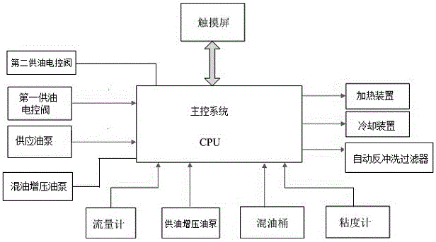
[0037] refer to figure 1 , the marine fuel oil supply device includes a mixed oil tank 9, an oil tank 1 and a main control system, and the described oil tank 1 is selected from at least 2 or 3 kinds of diesel tanks, gas oil tanks and heavy oil tanks; in the mixed oil tank 9 An oil mixing pipeline 5 is provided between the oil tank 1 and an oil supply pipeline 14 is provided between the oil mixing barrel 9 and the engine;

[0038] The oil mixing pipeline 5 is provided with a first oil supply electric control valve 2, a filter 3, an oil supply pump 18 and a flow meter 8 in sequence according to the direction of oil delivery;

[0039] The oil supply pipeline 14 is provided with an oil supply booster pump 7, a second oil supply electric control valve 19, and a viscometer 12 in sequence according to the oil delivery direction; A heating device 11 and a cooling device 10 are arranged in parallel; two oil supply booste...

Embodiment 3

[0042] Embodiment 3, in the marine fuel supply device described in Embodiment 1 or 2: the oil-mixing booster pump 4 is also connected in parallel on the supply oil pump 18, and the oil-mixing booster pump 4 is connected to the CPU through a signal line. There are 2 permanent oil-mixing booster oil pumps 7, one for constant and one for standby.

Embodiment 4

[0043] Embodiment 4, in a kind of marine fuel oil supply device described in embodiment 1 or 2 or 3: also be provided with automatic backwash filter 13 on the fuel supply pipeline 14 of the rear stroke of viscometer 12, automatic backwash filter 13 13 is connected with the CPU through a signal line.


PUM


Abstract

A marine fuel oil supply device comprises an oil mixing barrel, an oil cabinet and a master control system. An oil mixing pipeline is arranged between the oil mixing barrel and the oil cabinet. An oil supply pipeline is arranged between the oil mixing barrel and an engine, and the oil mixing pipeline is provided with a first oil supply electric control valve, a filter, a supply oil pump and a flow meter. The oil supply pipeline is provided with an oil supply pressurizing oil pump, a second oil supply electric control valve and a viscometer. A heating device and a cooling device are further connected between the second oil supply electric control valve and the viscometer in parallel. The master control system comprises a CPU. The oil mixing barrel, the first oil supply electric control valve, the supply oil pump, the flow meter, the oil supply pressurizing oil pump, the second oil supply electric control valve and the viscometer are connected with the CPU through signal lines. The invention further provides a marine fuel oil supply method. By means of the marine fuel oil supply device and method, heavy oil or diesel oil or gas oil is provided for a power generator of a ship, the fuel oil amount, pressure and viscosity can be adjusted according to needs, and the marine fuel oil supply device and method have the beneficial effects that the fuel oil quality is improved, the fuel oil efficiency is improved, the fuel oil cost is reduced, and the engine is better protected.

Description

technical field [0001] The invention relates to marine equipment, in particular to a marine fuel oil supply device and method. Background technique [0002] The power engine of the main engine in a large ship mainly uses gas oil, diesel oil and heavy oil as fuel, and the oil supply devices of the three kinds of oil are scattered in various positions of the engine room. Devices cannot be controlled cooperatively as a whole device. Its main defects are as follows: [0003] (1) The control method is old and the control effect is not good. [0004] (2) The degree of automation is not high, and it is impossible to respond in time, which affects the operating efficiency of the entire system. [0005] (3) The control is relatively scattered, and it is easy to operate incorrectly. [0006] (4) The pressure and viscosity values ​​of different oils cannot be provided to the engine according to a unified standard. Contents of the invention [0007] The technical problem to be so...

Claims


Application Information

Patent Timeline
IPC IPC(8): F02M37/04F02D19/06F02D41/00
CPCF02D19/0602F02D19/0605F02D19/0607F02D19/0613F02D19/0657F02D41/0025F02M37/0064F02M37/04Y02T10/30
Inventor 郑锐周军林晨咸云飞黄斌颜耀王圣东吴茂传田亚丽郑美红董奇
Owner 中船重工信息科技有限公司
Learn More