
Feeding clamping device

A material clip and clip arm technology, applied in the field of automation equipment, can solve the problems of high production cost, slow action process, complex structure, etc., and achieve the effects of high clamping efficiency, firm clamping and strong wear resistance.

Inactive Publication Date: 2016-12-07
吴道华
View PDF0 Cites 7 Cited by
  • Summary
  • Abstract
  • Description
  • Claims
  • Application Information

AI Technical Summary

Problems solved by technology

However, most of the current pick-up mechanisms are completed by two horizontal and vertical cylinders. Not only the action process is slow, the efficiency is low, it is not easy to control, the structure is complicated, and the production cost is relatively high.

Method used


Image

  • Feeding clamping device

Examples


Embodiment Construction

[0010] The present invention will be described in further detail below through specific implementation examples and in conjunction with the accompanying drawings.

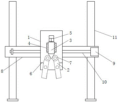
[0011] figure 1 Shown is the feeding and clamping device provided by the present invention, including two columns 11, a beam 8 mounted on the two columns 11, and a clamping mechanism mounted on the beam 8; the clamping mechanism includes a vertical plate 1, mounted on the vertical The two opposite clamping arms 2 on the lower part of the board 1, and the driving block 3 installed on the upper part of the vertical board 1; 4. The upper end of the driving block 3 is connected to the cylinder 5; the middle parts of the two clamping arms 2 are hinged to the vertical plate 1, and the two sides of the clamping arms 2 facing away from each other are respectively connected to the two sides of the vertical plate 1 with springs 6; The upper end of the clamp arm 2 is hinged with a roller 7, and the opposite surface of the lo...


PUM


Abstract

The invention discloses a feeding clamping device and belongs to the field of automation equipment. The feeding clamping device comprises two stand columns, a cross beam mounted on the two stand columns, and a clamping mechanism mounted on the cross beam. The clamping mechanism comprises a vertical plate, two oppositely arranged clamping arms mounted on the lower portion of the vertical plate, and a drive block mounted on the upper portion of the vertical plate. The drive block can slide up and down along the vertical plate. Guide plates located on the two sides of the drive block correspondingly are arranged on the vertical plate. An air cylinder is connected to the upper end of the drive block. The middles of the two clamping arms are hinged to the vertical plate. The sides, away from each other, of the two clamping arms are connected with two sides of the vertical plate through springs correspondingly. Idler wheels are hinged to the upper ends of the two clamping arms correspondingly. The opposite faces of the lower ends of the two clamping arms are clamping faces. The clamping faces are each in a serrated shape. The lower end of the drive block stretches into the space between the idler wheels of the two clamping arms. The two sides of the lower end of the drive block are provided with wedge-shaped faces making contact with the corresponding idler wheels. The clamping mechanism can slide along the cross beam. The structure is simple, the clamping efficiency is high, and the cost is lowered.

Description

technical field [0001] The invention relates to the field of automation equipment, in particular to a material loading and clamping device. Background technique [0002] In the process of mechanical manufacturing, picking equipment is usually a must for automated production lines, which can not only reduce manual labor, improve the degree of automation, but also greatly improve efficiency. However, most of the current pick-up mechanisms are completed by two horizontal and vertical cylinders. Not only the action process is slow, the efficiency is low, it is difficult to control, the structure is complicated, and the production cost is relatively high. Contents of the invention [0003] The object of the present invention is to provide a loading and clamping device to solve the above problems. [0004] In order to achieve the purpose of the present invention, the technical solution adopted is: a loading and picking device, including two columns, a beam mounted on the two co...

Claims


Application Information

Patent Timeline
Patent Type & Authority Applications(China)
IPC IPC(8): B25J15/02B25J9/02
CPCB25J9/026B25J15/022
Inventor 吴道华
Owner 吴道华
Learn More