
Split-type ratchet wrench

A ratchet wrench, split-type technology, applied in the field of wrenches, can solve problems such as the inability to screw and disassemble threaded connectors in closed systems, and achieve the effects of improving operational safety, avoiding bad force effects, and avoiding easy slippage

Active Publication Date: 2016-12-07
黑龙江技师学院
View PDF7 Cites 4 Cited by
  • Summary
  • Abstract
  • Description
  • Claims
  • Application Information

AI Technical Summary

Problems solved by technology

[0004] The present invention aims to solve the problem that the existing socket ratchet wrench cannot realize the screwing and disassembly of the threaded connection parts of the closed system, and further provides a split ratchet wrench

Method used


Image

  • Split-type ratchet wrench
  • Split-type ratchet wrench
  • Split-type ratchet wrench

Examples


specific Embodiment approach 1

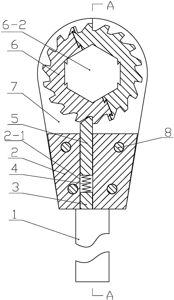
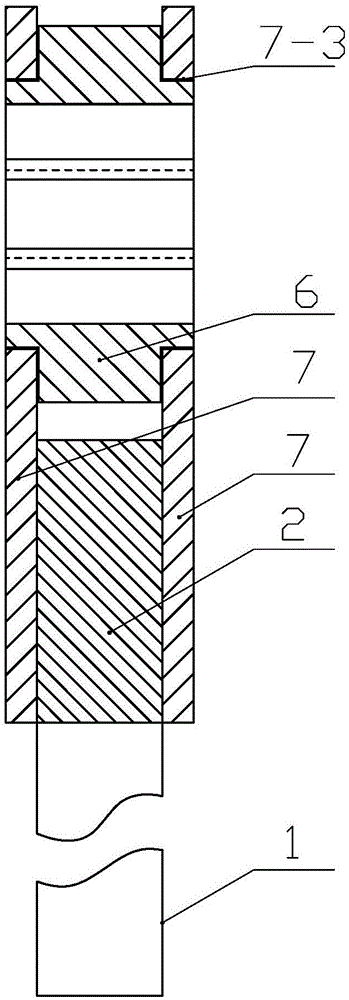
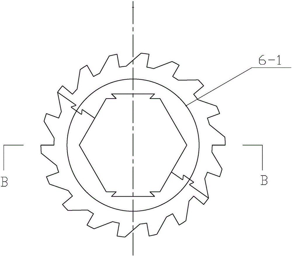
[0021] Specific implementation mode one: combine Figure 1 to Figure 8 Describe this embodiment, a split type ratchet wrench of this embodiment, including a handle 1, a fixed core 2, a plug 3, a spring 4, and a pawl 5, one end of the handle 1 is fixedly connected to one end of the fixed core 2, the The inside of the fixed core 2 is provided with a first through hole 2-1, the axis of the first through hole 2-1 is arranged parallel to the axis of the handle 1, and the plug 3 and the spring 4 are installed on the bottom of the fixed core 2 sequentially from bottom to top. In the first through hole 2-1, one end of the ratchet 5 is in contact with one end of the spring 4, and the other end surface of the ratchet 5 is an inclined plane. It also includes a split ratchet 6 and a two-component split positioning plate 7. The one-piece ratchet 6 includes two half-wheels 6-1 connected head to tail through the dovetail chute, and the center of the split-type ratchet 6 is provided with a fi...

specific Embodiment approach 2

[0025] Specific implementation mode two: combination Figure 1 to Figure 5 To illustrate this embodiment, the split ratchet 6 is positioned above the ratchet 5 through the two-component positioning plate 7 , and the hubs of the split ratchet 6 are in clearance fit with the two second through holes 7 - 3 . In such a design, the arc-shaped groove 7-2 mainly serves to limit the radial position of the ratchet to realize the rotation of the ratchet around the ratchet axis. Other compositions and connections are the same as those in the first embodiment.

specific Embodiment approach 3

[0026] Specific implementation mode three: combination figure 1 , image 3 and Figure 9 To illustrate this embodiment, a split type ratchet wrench also includes a split type inner sleeve 9, and the split type inner sleeve 9 includes two half sleeves 9-1 that are in close contact with each other. The first polygonal through hole 6-2 of the ratchet 6 cooperates, and the split inner sleeve 9 is fixedly connected in the first polygonal through hole 6-2 through the dovetail chute, and the center position of the split inner sleeve 9 is along its A second polygonal through hole is opened in the axial direction. With this design, split inner sleeves 9 of corresponding sizes can be nested according to different sizes of threaded connectors (such as nuts) during use, so that the same ratchet wrench can be used to assemble and disassemble threaded connectors of different sizes, effectively reducing Tool kit storage space saves cost and improves work efficiency. The outline of the sec...


PUM


Abstract

The invention discloses a split-type ratchet wrench, belongs to the field of machinery, and solves the problem that the conventional socket ratchet wrench cannot screw for mounting and detaching a threaded connecting component of a closed system. The split-type ratchet wrench comprises a split-type ratchet and two sets of split-type positioning plates, wherein the split-type ratchet comprises two half wheels which are connected end to end through dovetailed sliding slots; a first polygonal through hole is axially formed in the central position of the split-type ratchet; the other end of a pawl is inserted into one of toothed grooves of the split-type ratchet; the two sets of split-type positioning plates are symmetrically arranged at the two ends of the split-type ratchet; each set of split-type positioning plate comprises two oppositely-arranged half plates; two arc-shaped grooves are oppositely formed in the upper parts of the two oppositely-arranged half plates; the two oppositely-arranged arc-shaped grooves form a second through hole; the two ends of a hub of the split-type ratchet are inserted into the second through hole; the lower part of each half plate is fixedly connected with a fixing core through pin shafts. The split-type ratchet wrench is used for screwing the threaded connecting component.

Description

technical field [0001] The invention relates to a wrench, in particular to a split ratchet wrench. Background technique [0002] The ratchet wrench is a manual screw tightening tool. When the size of the screw or nut is large or the working position of the wrench is very narrow, a ratchet wrench can be used. This wrench has a small swing angle and can tighten and loosen screws or nuts. The nut is turned and turned manually by reciprocating swing, which is convenient and quick, labor-saving and time-saving, can be loosened and tightened, has strong applicability, and can conveniently adjust the use angle. When the existing ratchet wrench is used, the polygonal inner hole of the ratchet is set on a threaded part (such as a screw) whose shape and size match, and the handle is rotated to realize the loosening and tightening operation of the threaded part, and the handle is rotated in the opposite direction. At this time, due to the friction of the thread mating surface of the ...

Claims


Application Information

Patent Timeline
Patent Type & Authority Applications(China)
IPC IPC(8): B25B13/46
CPCB25B13/463
Inventor 李宝柱邹兆伟
Owner 黑龙江技师学院
Learn More