A bypass metal removal device

A technology of metal removal and metal removal, applied in the direction of magnetic separation, solid separation, chemical instruments and methods, etc., can solve the problems of wrongly removing magnetite and ineffective removal of metal impurities, etc., and achieve the effect of ensuring the operation rate

Active Publication Date: 2017-11-24
MCC NORTH (DALIAN) ENG TECH CO LTD
View PDF10 Cites 0 Cited by
  • Summary
  • Abstract
  • Description
  • Claims
  • Application Information

AI Technical Summary

Problems solved by technology

[0005] Aiming at the problem that current electromagnetic iron removal equipment cannot effectively remove metal impurities in solid materials and may mistakenly remove magnetite in solid materials, the present invention provides a bypass metal removal device, the bypass metal removal device The device includes: a first metal detector, a control box, a driving mechanism, a metal removing mechanism, a metal discharge part and a second metal detector;

Method used


Image

  • A bypass metal removal device
  • A bypass metal removal device
  • A bypass metal removal device

Examples


Embodiment Construction

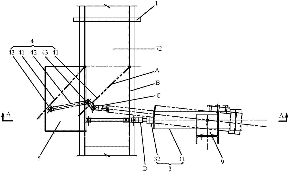
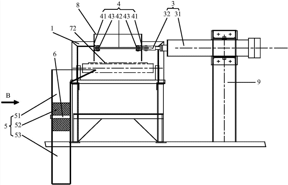
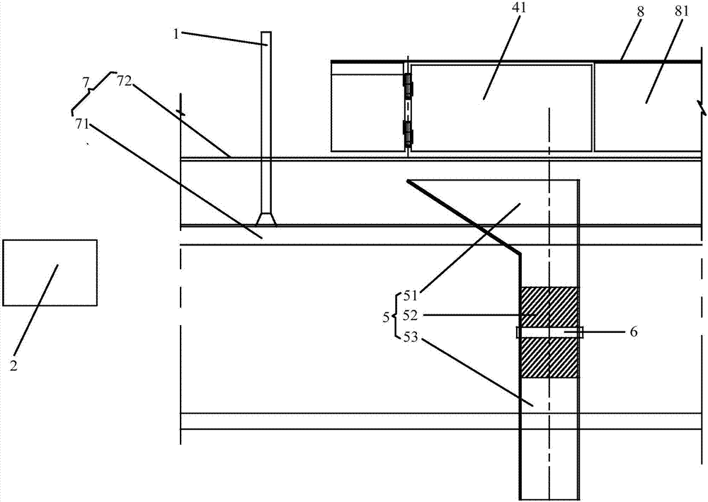
[0037] In order to solve the problems existing in the prior art, such as figure 1 shown, and see figure 2 and image 3 , the embodiment of the present invention provides a bypass metal removal device, the bypass metal removal device includes: a first metal detector 1, a control box 2, a drive mechanism 3, a metal removal mechanism 4, a metal discharge part 5 and a second metal detector 6;

[0038] The first metal detector 1 is installed on the longitudinal beam 71 of the belt conveyor 7, and is used to detect metal impurities transported on the transport track 72 of the belt conveyor 7, and sends a first alarm signal; the control box 2 is used for Receive the first alarm signal and send the first control instruction to the drive mechanism 3 according to the first alarm signal; The control command drives the metal removal mechanism 4 to move, so that the material delivery path of the metal removal mechanism 4 is separated from the transport track 72; When separated from th...


PUM


Abstract

The invention discloses a by-pass metal removing device. The by-pass metal removing device comprises a first metal detector, a control cabinet, a driving mechanism, a metal removing mechanism, a metal discharging part and a second metal detector; the first metal detector is used for detecting metal impurities on a conveying track and sends first alarm signals; the control cabinet receives the first alarm signals and sends first control commands to the driving mechanism; the driving mechanism drives the metal removing mechanism to move according to the first control commands, so that a conveying path of the metal removing mechanism is separated from the conveying track, and the metal impurities are conveyed along the conveying path of the metal removing mechanism and fall into the metal discharging part; the second metal detector is used for detecting the metal impurities falling into the metal discharging part and sends second alarm signals; the control cabinet receives the second alarm signals and sends second control commands to the driving mechanism; and the driving mechanism drives the metal removing mechanism to move according to the second control commands, so that the conveying path of the metal removing mechanism overlaps with the conveying track.

Description

technical field [0001] The invention relates to the technical field of mineral processing, in particular to a bypass metal removal device. Background technique [0002] In the beneficiation plant, it is necessary to use medium and fine crushing equipment to carry out medium or fine crushing operations on the mined solid materials, but in the process of handling and transporting solid materials before crushing, some iron nuggets, iron brazing, iron rods, etc. are often mixed in Iron impurities and some other metal impurities, these metal impurities are difficult to crush, and will cause great harm to the medium and fine crushing equipment. For example, if these metal impurities enter the standard cone crusher or short head cone crusher, they will destroy the crushing cavity If these metal impurities enter the high-pressure roller mill equipment, they will damage the roller surface and teeth, and even get stuck between the two rollers. cause the equipment to stop running. ...

Claims


Application Information

Patent Timeline
Patent Type & Authority Patents(China)
IPC IPC(8): B03C1/18
CPCB03C1/18
Inventor 李国洲
Owner MCC NORTH (DALIAN) ENG TECH CO LTD
Why Eureka
Try Eureka