
DDD MOS device structure and manufacturing method thereof

A technology of device structure and manufacturing method, applied in the manufacture of DDDMOS device structure, in the field of DDDMOS device structure, can solve the problems of limiting the application range of DDDMOS devices and low breakdown voltage

Active Publication Date: 2016-11-30
SHANGHAI HUAHONG GRACE SEMICON MFG CORP
View PDF4 Cites 1 Cited by
  • Summary
  • Abstract
  • Description
  • Claims
  • Application Information

AI Technical Summary

Problems solved by technology

The turn-off breakdown voltage of the existing DDD MOS structure is low, which limits the application range of DDD MOS devices

Method used


Image

  • DDD MOS device structure and manufacturing method thereof
  • DDD MOS device structure and manufacturing method thereof
  • DDD MOS device structure and manufacturing method thereof

Examples


Embodiment Construction

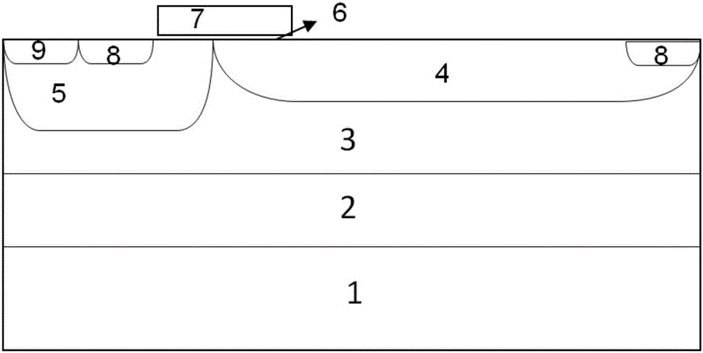
[0035] Such as figure 1 As shown, the DDD MOS device structure provided by the present invention includes: an N-type buried layer above the P-type substrate, an N-type epitaxy above the N-type buried layer, and an N-type drift region and a P well arranged in parallel on the top of the N-type epitaxy , the upper part of the P well is arranged in parallel with an N-type heavily doped region and a P-type heavily doped region, the gate oxide layer is located above the N-type drift region and the P well, the polysilicon gate is located above the gate oxide layer, and the second N-type heavily doped region It is arranged on the side of the upper part of the N-type drift region away from the polysilicon gate; wherein, the first N-type heavily doped region, the second N-type heavily doped region, and the P-type heavily doped region have boron impurities, and the polysilicon gate below There are boron impurities in the outer N-type drift region and P well. refer to Figure 7 As shown...


PUM


Abstract

The invention discloses a DDD MOS device structure. The DDD MOS device structure comprises an N-type buried layer on a P-type substrate, an N-type epitaxial layer on the N-type buried layer, an N-type drift area and a P trap which are arranged side by side on at the upper portion of the N-type epitaxial layer, and N-type heavily-doped areas and a P-type heavily-doped area which are arranged side by side at the upper portion of the P trap. A gate oxide layer is disposed on the N-type drift area and the P trap, a polysilicon grid is disposed on the gate oxide layer, the second N-type heavily-doped area is arranged at one side, away from the polysilicon grid, at the upper portion of the N-type drift area, the first N-type heavily-doped area, the second N-type heavily-doped area and the P-type heavily-doped area are internally provided with boron impurities, and the N-type drift area and the P trap below the polysilicon grid are internally provided with the boron impurities. The invention also discloses a manufacturing method of the DDD MOS device structure. According to the invention, under the condition that device turning-on breakdown voltages are not reduced, the device turning-off breakdown voltages are improved.

Description

technical field [0001] The invention relates to the field of semiconductors, in particular to a DDD MOS (Double Diffused DrainMOSFET, high voltage double diffused drain device) device structure. The invention also relates to a manufacturing method of the DDD MOS device structure. Background technique [0002] DDD MOS (Double Diffused Drain MOSFET) high-voltage double-diffused drain devices are widely used in circuit output interfaces, LCD drive circuits, etc., and their operating voltage is about 10-20V. DDD MOS is easily compatible with the traditional CMOS process, the process is simpler than LD MOS, and the manufacturing cost is lower. [0003] The existing DDD MOS structure includes: N-type buried layer above the P-type substrate, N-type epitaxy above the N-type buried layer, N-type drift region and P well arranged in parallel on the upper part of the N-type epitaxy, and parallel arranged on the upper part of the P well An N-type heavily doped area and a P-type heavily...

Claims


Application Information

Patent Timeline
IPC IPC(8): H01L29/78H01L21/336
CPCH01L29/66689H01L29/7816
Inventor 段文婷
Owner SHANGHAI HUAHONG GRACE SEMICON MFG CORP
Learn More