
Bending device of bending tester

A bending test and bending device technology, used in measuring devices, instruments, and testing the strength of materials by applying a stable bending force, can solve the problems that affect the measurement effect and the bending device is easy to rotate, and improve the test accuracy. , easy to replace, reduce the effect of variables

Inactive Publication Date: 2016-11-30
弘毅天承知识产权股份有限公司
View PDF0 Cites 0 Cited by
  • Summary
  • Abstract
  • Description
  • Claims
  • Application Information

AI Technical Summary

Problems solved by technology

[0003] The invention provides a bending device of a bending tester, which solves the problem that the bending device of the existing wire bending tester is prone to rotation and affects the measurement effect

Method used


Image

  • Bending device of bending tester
  • Bending device of bending tester
  • Bending device of bending tester

Examples


Embodiment 1

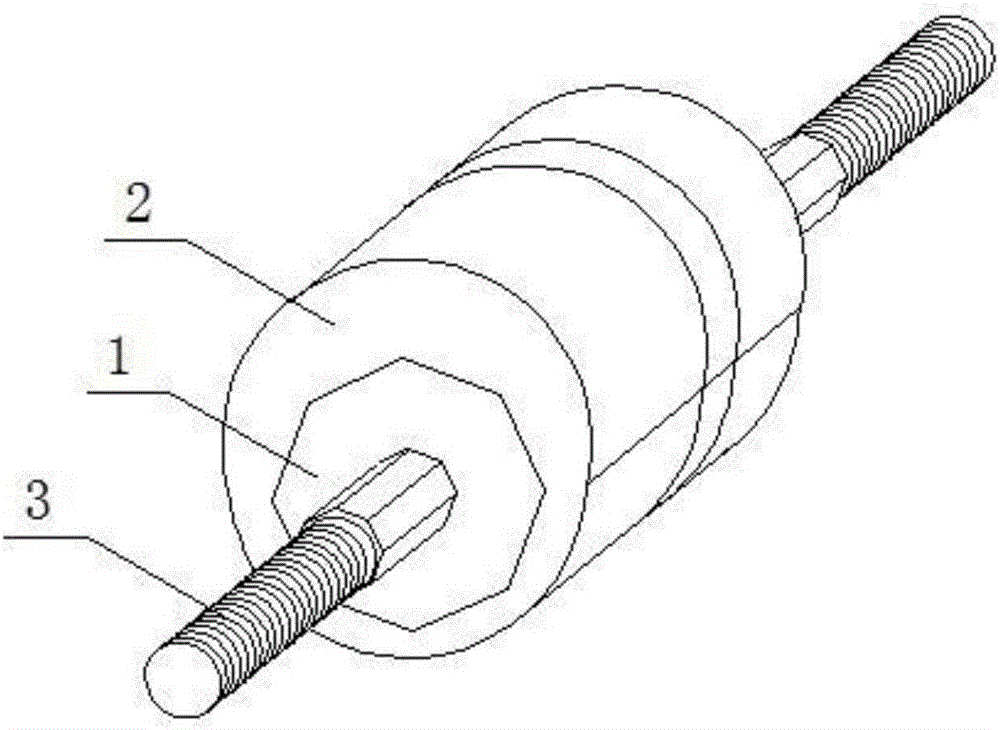
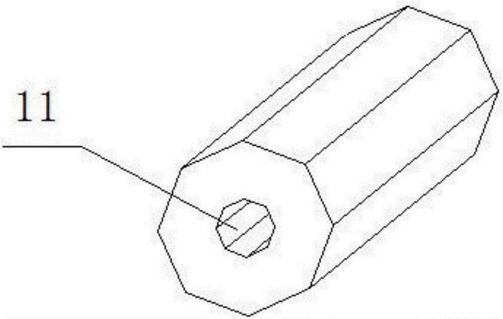
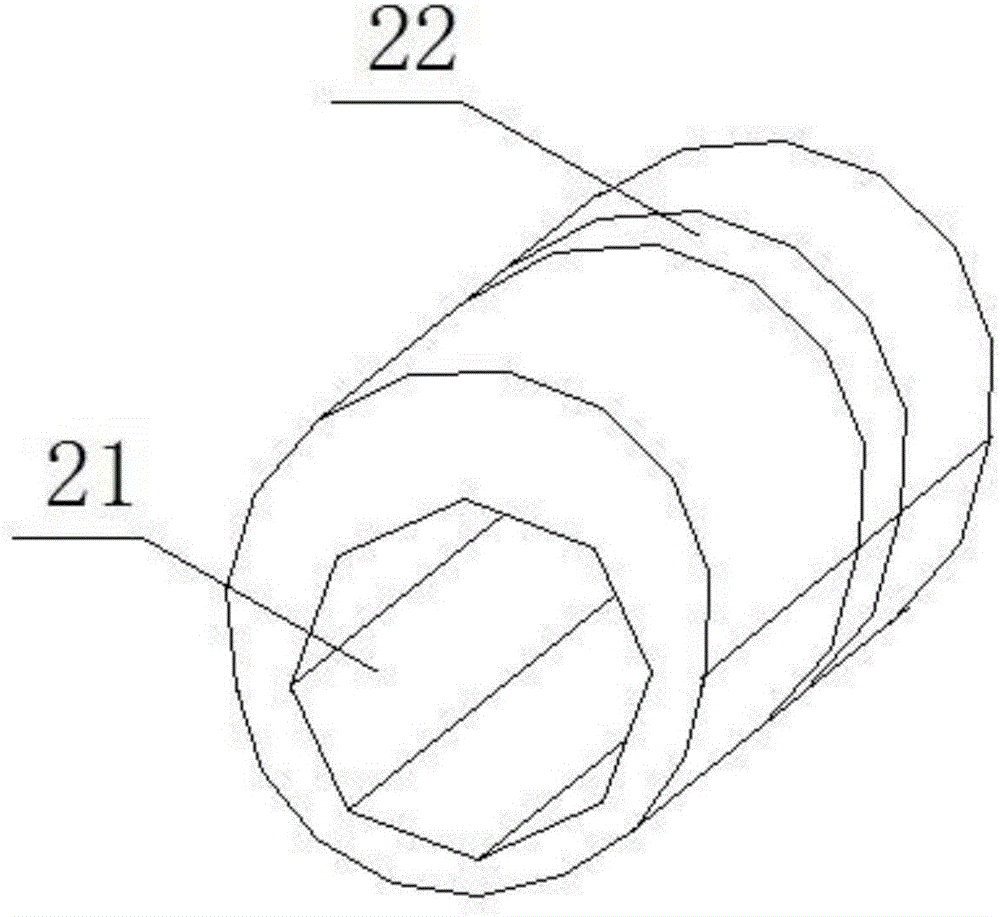
[0026] Such as Figure 1-Figure 3 As shown, a bending device of a bending tester is installed in the installation groove on the wire bending tester, and the two sides of the installation groove are provided with regular polygonal through holes, including a through hole column 1, and the through hole A fixed through hole 11 is arranged at the central axis of the hole post 1, and the axis of the fixed through hole 11 coincides with the through hole post 1. The fixed through hole 11 is provided with a regular polygonal fixed rod 3, and the two fixed rods 3 The end extends to the polygonal through holes on both sides of the installation groove; the through hole column 1 is covered with a wire bending sleeve 2, and the outer surface of the wire bending sleeve 2 is provided with a wire groove 22, and the through hole column 1. The length of the wire bending sleeve 2 is equal to the length of the installation groove.

[0027] The installation sequence of the bending device of a bend...

Embodiment 2

[0030] Further optimized on the basis of the bending device of a bending tester described in Example 1, the central axis of the wire bending sleeve 2 is provided with a connecting through hole 21, and the connecting through hole 21 is connected with the bending of the wire rod. The axis of the sleeve 2 coincides, and the through-hole column 1 is set in the connecting through-hole 21, and the shape and size of the connecting through-hole 21 and the through-hole column 1 are consistent. The setting of this embodiment makes the wire bending sleeve and the through-hole There are no gaps between the columns and no mutual movement occurs.

Embodiment 3

[0032] On the basis of the bending device of a kind of bending tester described in embodiment 1, it is further optimized. The cross-sections of the connecting through hole 21 and the fixing through hole 11 are all set as regular polygons. The setting of this embodiment can ensure that the through hole There is no relative sliding between the column, the wire bending sleeve and the fixed rod.


PUM


Abstract

The invention discloses a bending device of a bending tester and relates to the field of product performance testing devices. The bending device is installed inside an installation groove on a wire bending tester. Two sides of the installation groove are provided with regular polygon through-holes including through-hole columns. A fixed through hole is arranged at the middle axle of the through-hole column. The fixed through hole overlaps the axis of the through-hole column. the fixed through hole sleeves a regular polygon dead lever, two ends of which extends to the outside of the regular polygon through-holes at two sides of the installation groove. A wire bending sleeve sleeves the through-hole column. The external surface of the wire bending sleeve is provided with a wire groove. Length of the through-hole column and the wire bending sleeve is equal to length of the installation groove. The wire bending sleeve is easy to replace for bending tests of wires of different curvatures. Thus, a wire is effectively prevented from sliding on the bending device. Due to no turning between the bending device and the installation groove on the wire bending tester, variables are minimized, and testing precision is enhanced.

Description

technical field [0001] The invention relates to the field of product performance testing devices, in particular to a bending device of a bending tester. Background technique [0002] Wire and cable is a wire product used to transmit electric (magnetic) energy, information and realize the conversion of electromagnetic energy. Wire and cable can be referred to as cable for short. Cables are often bent into various shapes during use. After repeated bending, the wire core in the cable may be broken, causing the cable to break. Fracture after bending. However, when the existing wire bending testing machine is testing, if the tension at both ends of the cable is different, a moment will inevitably be given to the bending device, so that the bending device is prone to rotation, causing the stress point of the cable to shift. Therefore, the measurement effect is affected; secondly, the existing wire bending testing machine often only has one curvature detection, and the detection ...

Claims


Application Information

Patent Timeline
Patent Type & Authority Applications(China)
IPC IPC(8): G01N3/20
CPCG01N3/20G01N2203/0023
Inventor 樊明伟
Owner 弘毅天承知识产权股份有限公司
Learn More