
Rotating joint

A technology of rotating joints and spindles, which is applied to rotating joints. field, it can solve problems such as institutional swelling, complexity, and lack of data links, and achieve the effect of high safety performance and wide application prospects

Active Publication Date: 2016-11-23
昆山市东浩塑胶机械有限公司
View PDF5 Cites 0 Cited by
  • Summary
  • Abstract
  • Description
  • Claims
  • Application Information

AI Technical Summary

Problems solved by technology

However, the electric ring transmits energy through the sliding contact of the graphite brush. The disadvantage is that the sliding will bring sparks, poor contact, and the service life is not long. Especially for data signals, it will cause the loss of the data link. There is another disadvantage. That is, the body will become swollen and complicated
[0003] After researching the latest wireless power transmission technology, wireless Wifi, Bluetooth, and infrared data transmission technology, it is found that in the working environment, affected by various sports conditions, the efficiency of wireless power transmission will not be high, and the data signal will be time-consuming. Intermittent, sometimes weak and sometimes strong, it is inevitable that there will be unstable production, and in severe cases, there will be production accidents

Method used


Image

  • Rotating joint

Examples


Embodiment Construction

[0023] In view of the deficiencies in the prior art, the inventor of this case was able to propose the technical solution of the present invention after long-term research and extensive practice. The technical solution, its implementation process and principle will be further explained in conjunction with the accompanying drawings as follows.

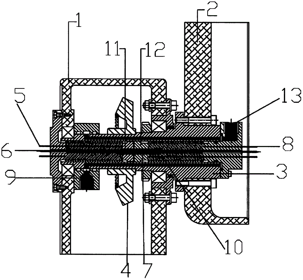
[0024] see figure 1 , the present invention discloses a rotary joint, comprising a relatively stationary first mechanical arm 1 and a circularly moving mechanical arm 2 relative to the first mechanical arm 1, a main shaft 3 with a hollow structure and a power input device 4, the main shaft 3 contains a first conductor 11 and a second conductor 12 wound with a coil, and the first conductor 11 and the second conductor 12 are separated from each other, the first conductor 11 rotates concentrically with respect to the main shaft 3, the second The two conductors 12 are stationary relative to the main shaft 3, the first conductor 11 and the ...


PUM


Abstract

The invention discloses a rotating joint which comprises a spindle having a hollow structure and a power input device. A first conductor and a second conductor are accommodated in the spindle in a winding manner, the first conductor is separated from the second conductor, the first conductor rotates concentrically relative to the spindle, the second conductor is static relative to the spindle, the first conductor and the second conductor rotate concentrically, and the spindle is provided with a signal input end and a signal output end. The rotating joint is capable of transmitting electric energy, data signals and pneumatic energy without limitation of rotating angles, high in security and wide in application range.

Description

technical field [0001] In particular, the invention relates to a swivel joint. Background technique [0002] At present, the transmission of electric energy and data signals to the rotating body is usually through direct wiring on the periphery, but the rotation angle cannot exceed plus 360° and minus 360°. If this angle is exceeded, a rotating electric ring is generally used. However, the electric ring transmits energy through the sliding contact of the graphite brush. The disadvantage is that the sliding will bring sparks, poor contact, and the service life is not long. Especially for data signals, it will cause the loss of the data link. There is another disadvantage. That is, the organization will become swollen and complicated. [0003] After researching the latest wireless power transmission technology, wireless Wifi, Bluetooth, and infrared data transmission technology, it is found that in the working environment, affected by various sports conditions, the efficienc...

Claims


Application Information

Patent Timeline
Patent Type & Authority Applications(China)
IPC IPC(8): H01R39/02
CPCH01R39/02
Inventor 何正明
Owner 昆山市东浩塑胶机械有限公司
Learn More