Optical fiber strain sensor and preparation method thereof

A fiber optic strain and sensor technology, applied in instruments, optical devices, measuring devices, etc., can solve the problems of temperature sensitivity, expensive system, and lower detection accuracy, and achieve the effect of simple preparation and low cost

Active Publication Date: 2016-11-23
黄辉 +2
View PDF8 Cites 0 Cited by
  • Summary
  • Abstract
  • Description
  • Claims
  • Application Information

AI Technical Summary

Problems solved by technology

[0003] At present, fiber optic strain sensors usually use a fiber grating structure, but strain sensors with a fiber grating structure need tunable lasers or spectrum analyzers to monitor the reflection wavelength, so the system is expensive
In addition, the fiber grating is sensitive to temperature. Due to thermal expansion and contraction, the period of the grating will change, and the corresponding reflection wavelength will also change with temperature, thereby reducing the detection accuracy.

Method used


Image

  • Optical fiber strain sensor and preparation method thereof
  • Optical fiber strain sensor and preparation method thereof

Examples


Embodiment Construction

[0034] The present invention will be described in detail below in conjunction with the embodiments and the accompanying drawings. It should be noted that the described embodiments are only intended to facilitate the understanding of the present invention, rather than limiting it in any way.

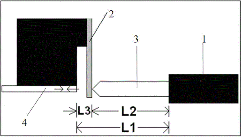
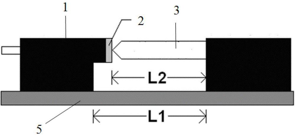
[0035] See attached figure 1 It is a schematic diagram (top view) of a kind of optical fiber strain sensor of the present embodiment; figure 2 It is a schematic diagram (side view) of an optical fiber strain sensor in this embodiment. An optical fiber strain sensor, comprising at least two fixed brackets 1, an optical fiber device 4, a transmission rod 3, and a cantilever beam 2, one end of the transmission rod 3 is fixed on one of the fixed brackets 1, and the other end of the transmission rod 3 is connected to the cantilever beam 2 For contact, the fiber optic device 4 and the cantilever beam 2 are fixed on another fixed bracket 1 , the fiber optic device 4 is used to emit the detecti...


PUM


Abstract

The invention relates to an optical fiber strain sensor and a preparation method thereof. The optical fiber strain sensor is characterized by comprising at least two fixed brackets, an optical fiber device, a transmission rod and a cantilever beam, wherein one end of the transmission rod is fixed on one of the fixed brackets, the other end of the transmission rod is contacted with the cantilever beam, the optical fiber device and the cantilever beam are fixed on the other fixed bracket, and the optical fiber device is used for transmitting a detection beam and receiving a detection beam reflected back from the cantilever beam. The beneficial effect is that influences imposed on the sensor by the temperature can be reduced through changing the length and the thermal expansion coefficient of the transmission rod. The sensor provided by the invention has the advantages of tunability, simple preparation and low cost.

Description

technical field [0001] The invention relates to a strain sensor and a preparation method thereof, in particular to an optical fiber strain sensor and a preparation method thereof, which can be used to detect the deformation of an object. Background technique [0002] Optical fiber sensors use light as the carrier and optical fiber as the medium to sense and transmit external signals, and are suitable for detection of acceleration, pressure, and vibration in inflammable, explosive, high-temperature, and high-pressure environments [IEEE SensorsJournal, vol.8, PP.1184 -1193, 2008]. Due to its small size, light weight, easy installation, not easily corroded by chemical substances, free from electromagnetic radiation interference, and capable of remote sensing and multi-point sensing, fiber optic sensors are very suitable for strain detection and have been widely used in construction in animal health monitoring and smart materials. [0003] At present, fiber optic strain sensor...

Claims


Application Information

Patent Timeline
Patent Type & Authority Applications(China)
IPC IPC(8): G01B11/16
Inventor 黄辉渠波胡杰白敏
Owner 黄辉
Why Eureka
Try Eureka