
Damping adjustment device suitable for electrorheological damper

A damping adjustment and damper technology, which is applied in the direction of shock absorbers, shock absorbers, springs/shock absorbers, etc., can solve the problems that the damping force cannot be adjusted, the amplitude characteristics of the suspension are not considered, and the performance of the electrorheological fluid is affected.

Active Publication Date: 2016-11-23
徐州金沙滩机床配件有限公司
View PDF6 Cites 4 Cited by
  • Summary
  • Abstract
  • Description
  • Claims
  • Application Information

AI Technical Summary

Problems solved by technology

The electrorheological dampers of these three structures can improve the ride comfort and handling stability of the car by changing their own damping force according to different road conditions, but they cannot adjust the damping force well according to the suspension amplitude.
In practical engineering applications, when the electrorheological damper is working, it is only to quickly consume vibration energy, without considering the characteristics of the suspension amplitude (small amplitude frequency is fast, large amplitude frequency is slow), which will cause heat generation when the damper is working, which will further cause Affects the performance of the internal electrorheological fluid, making the suspension system work less than optimal

Method used


Image

  • Damping adjustment device suitable for electrorheological damper
  • Damping adjustment device suitable for electrorheological damper
  • Damping adjustment device suitable for electrorheological damper

Examples


Embodiment Construction

[0038] The specific embodiment of the present invention will be described in further detail by describing the embodiments below with reference to the accompanying drawings, the purpose is to help those skilled in the art to have a more complete, accurate and in-depth understanding of the concept and technical solutions of the present invention, and contribute to its implementation.

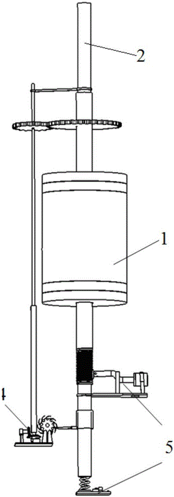
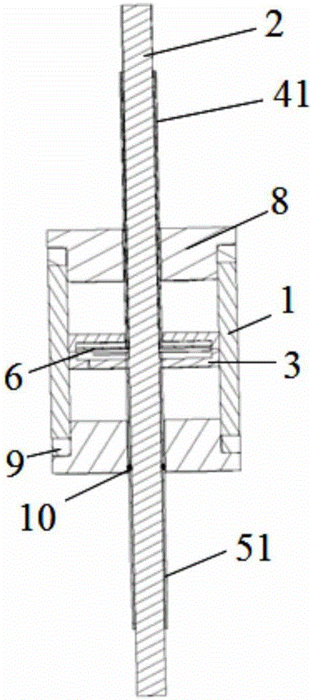
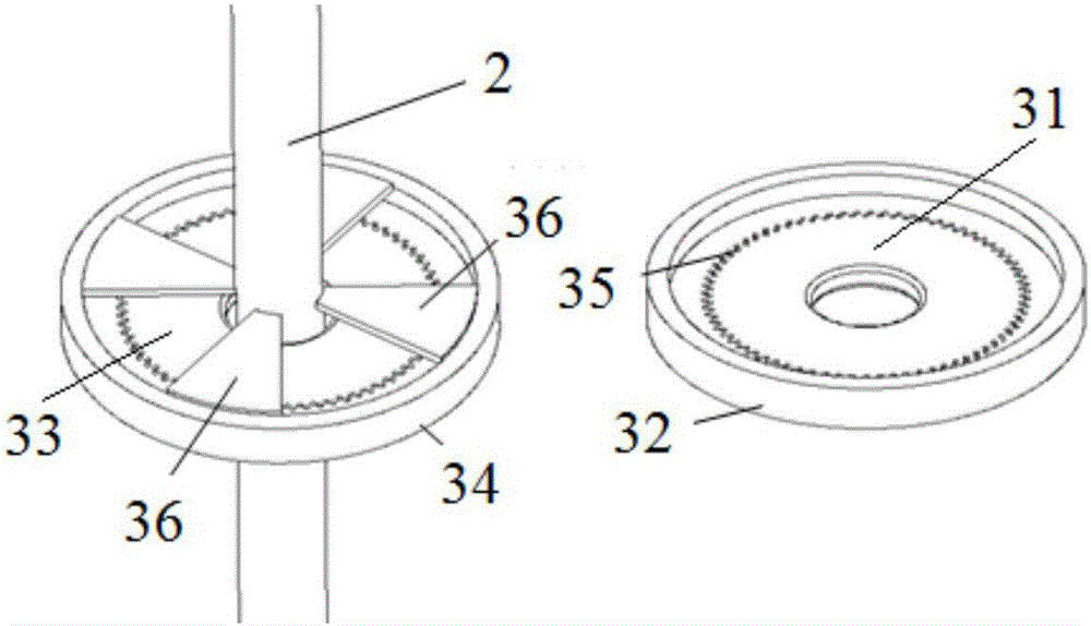
[0039] like figure 1 and figure 2 Shown is an electrorheological damper using the damping adjustment device of the present invention, which includes a cylinder 1, a piston rod 2, a piston assembly 3 and the damping adjustment device of the present invention. The cylinder 1 is a hollow cylindrical body, and the hollow part inside the cylinder 1 is a cylindrical inner cavity storing electrorheological fluid. The piston assembly 3 is arranged in the inner cavity of the cylinder 1, and the piston assembly 3 has a plurality of orifices 35 through which the electrorheological fluid passes. The pisto...


PUM


Abstract

The invention discloses a damping adjustment device suitable for an electrorheological damper. The damping adjustment device comprises first damping fins, second damping fins, a frequency damping adjustment device connected with the first damping fins and an amplitude damping adjustment device connected with the second damping fins, wherein the first damping fins and the second damping fins are rotatable, arranged in a piston assembly of the electrorheological damper and used for adjusting the number of throttling holes in opened or closed state. According to the damping adjustment device suitable for the electrorheological damper, as the first damping fins and the second damping fins are arranged in the piston assembly, and the number of the throttling holes in opened or closed state is adjusted through the first damping fins and the second damping fins, the damping force of the electrorheological damper can be changed, and the purpose of damping adjustment is achieved.

Description

technical field [0001] The invention belongs to the technical field of dampers, in particular, the invention relates to a damping adjustment device suitable for electrorheological dampers. Background technique [0002] At present, there are three main structures of electrorheological dampers used in suspension systems: single-rod single-cylinder structure, double-rod double-cylinder structure and rotary structure. The electrorheological dampers of these three structures can improve the ride comfort and handling stability of the car by changing their own damping force according to different road conditions, but none of them can adjust the damping force well according to the suspension amplitude. In practical engineering applications, when the electrorheological damper is working, it is only to quickly consume vibration energy, without considering the characteristics of the suspension amplitude (small amplitude frequency is fast, large amplitude frequency is slow), which will ...

Claims


Application Information

Patent Timeline
IPC IPC(8): F16F9/44F16F9/34
CPCF16F9/34F16F9/44F16F2228/066
Inventor 肖平江民高洪时培成胡红生凤志民韩利敏王勇张荣芸潘道远唐冶王建平刘桂武
Owner 徐州金沙滩机床配件有限公司
Learn More