
Rack clamping structure for half shaft

A rack and gear technology, which is applied in the rack clamping structure of the half shaft, can solve the problems of easy damage to the foam, easy damage to the half shaft, and increased costs, and achieve the effects of ensuring the quality of transportation, convenient use, and reducing bumps

Inactive Publication Date: 2016-11-23
CHONGQING JINYUHENG TECH
View PDF0 Cites 5 Cited by
  • Summary
  • Abstract
  • Description
  • Claims
  • Application Information

AI Technical Summary

Problems solved by technology

[0002] In the prior art, when transporting the half shaft, the half shaft is mostly worn on the transport frame or directly placed in the transport box. This method is easy to damage the inner and outer surfaces of the half shaft, especially on bumpy roads; of course, there are also The method of foam bottoming is adopted. Although this method solves the problem of the half shaft being damaged due to bumps and vibrations, the foam at the bottom is easy to damage, which is not conducive to repeated use, increases the cost and pollutes the environment, and its storage per unit area Low axle weight further increases shipping costs

Method used


Image

  • Rack clamping structure for half shaft

Examples


Embodiment Construction

[0009] The present invention will be further described below in conjunction with the drawings and embodiments:

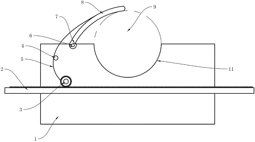
[0010] See figure 1 , A half-shaft rack clamping structure, comprising a base 1, a semicircular mounting groove 11 is opened on the base 1, the left side of the mounting groove 11, the base 1 and the curved One end of the shaped pressing plate 8 is hinged;

[0011] The other end of the curved pressing plate 8 is connected with a drawstring 5, and the drawstring 5 bypasses the wire groove 4 and is connected to the gear 3. Of course, a reel that rotates synchronously with the gear 3 can also be connected to the gear 3. , And then connect the drawstring 5 to the reel. The drawstring 5 should be made of inelastic material;

[0012] A pull plate 2 is provided under the gear 3, and a rack that meshes with the gear 3 is provided on the pull plate 2;

[0013] A torsion spring 7 is installed in the first hinge 6, and the torsion spring 7 generates a torsion force that turns the cu...


PUM


Abstract

The invention discloses a rack clamping structure for a half shaft. The rack clamping structure comprises a base, wherein a semicircular installation groove is formed in the base, and the base is hinged with one end of a curved pressing plate through a first hinge at the left side of the installation groove; the other end of the curved pressing plate is connected with a pull rope, the pull rope is connected with a gear after passing through a wire guide groove, a pull plate is arranged below the gear, and a rack engaged with the gear is arranged on the pull plate; and a torsional spring is installed in the first hinge, and the torsional spring generates a torsional force enabling the curved pressing plate to rotate towards the installation groove. The rack clamping structure disclosed by the invention is simple in structure, convenient to use, and capable of effectively reducing bump of the half shaft due to loose fixation, thus ensuring transport quality for the half shaft.

Description

Technical field [0001] The invention relates to a tool for clamping a half shaft when the half shaft is transported. Background technique [0002] In the prior art, most of the half-shafts are transported by putting the half-shaft on the transport rack or directly placed in the transport box. This method can easily damage the inner and outer surfaces of the half-shaft, especially on bumpy roads; The foam bottom is used. Although this method solves the problem of the half-shaft being damaged due to bumps and jitters, the foam at the bottom of the bottom is easily damaged, which is not conducive to multiple use, increases the cost and pollutes the environment, and its unit area is stored The semi-axle volume is low, which further increases the transportation cost. Summary of the invention [0003] In view of the above-mentioned shortcomings of the prior art, the technical problem to be solved by the present invention is to provide a half-shaft rack clamping structure to prevent it ...

Claims


Application Information

Patent Timeline
Patent Type & Authority Applications(China)
IPC IPC(8): B65D61/00B65D85/20B65D85/68
Inventor 杨兰明
Owner CHONGQING JINYUHENG TECH
Learn More