


Quick Research
Generate reliable direction feasibility study reports for your R&D in just a few steps.

Technical Q&A
Discover and master advanced knowledge NOW. Basics, ideas, possibilities, all at once.

Find Solutions
As an expert in R&D theories, this can generate solutions to your technical problems instantly.

Evaluate Feasibility
Analyze your overall solution with one click, know your potential R&D risks in advance.

Monitor Landscape
Get weekly tech updates, stay abreast of the latest tech innovations and key insights.
Plugging device having auxiliary contact
A technology of a plug-in device and an auxiliary contact is applied in the direction of a two-part connecting device, parts of the connecting device, coupling devices, etc., which can solve the problems of easy failure of the position sensor, high cost, complicated installation, etc., and achieves convenient connection and use cost. Low, the effect of ensuring normal operation
- Summary
- Abstract
- Description
- Claims
- Application Information
AI Technical Summary
Problems solved by technology
Method used
Image

Examples
Embodiment approach 1
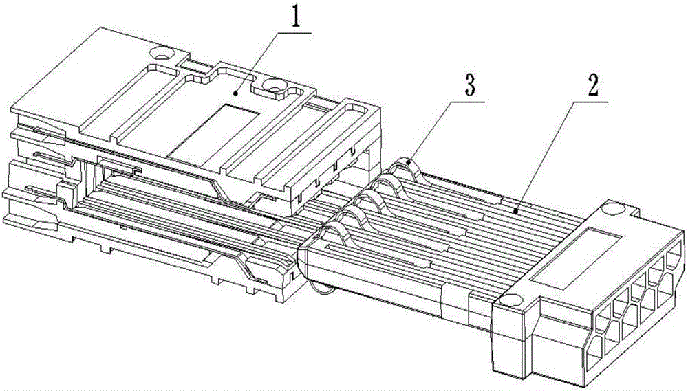
[0028] The auxiliary circuit plug-in is composed of plug 2 and socket 1. The plug 2 and the socket 1 are except for the electrical conductors used for electrical connection, and all the other main components are formed by one-time pressing of insulating flame-retardant plastics.
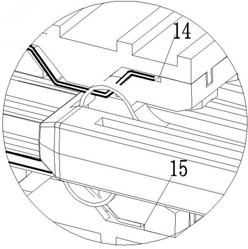
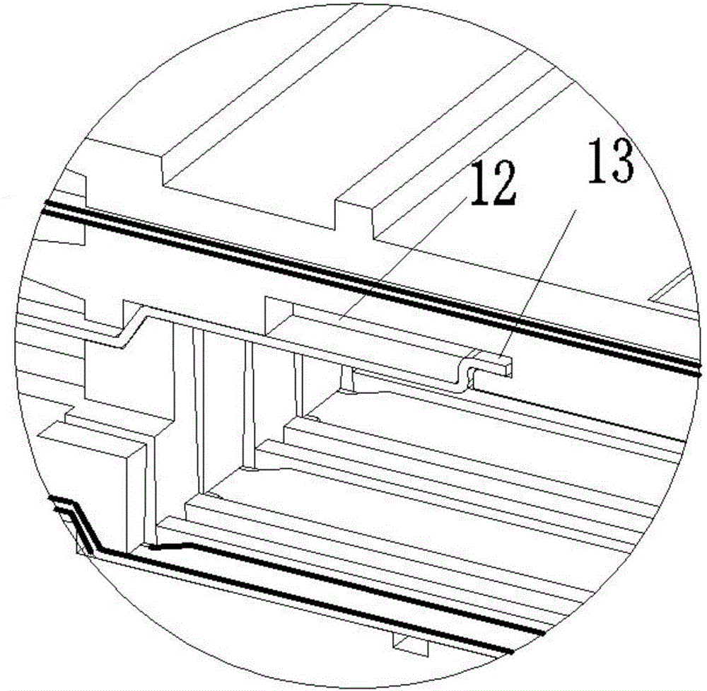
[0029] The plug 2 is press-fitted with a plug contact reed 3 with an arc-shaped contact 4 on the top (the plug contact point can be any form of contact guide point, and the present embodiment is preferably a plug contact reed 3 with an arc-shaped contact 4), There are two contact reeds 3 up and down, and an insulating plastic isolation layer is arranged between the two contact reeds 3 . The rear end of the plug 2 is a plug terminal 5, and the plug terminal 5 is provided with a connection hole 6 corresponding to the plug contact body. The structural design of the plug 2 is basically similar to the usual auxiliary circuit plugs of various types. Socket 1 internal pressure is equipped with upper conduc...
Embodiment approach 2
[0035] The difference between this embodiment and Embodiment 1 is that the upper, middle and lower conductive reeds are set as left, middle and right conductive reeds, and the plug contact points at the ends of the plug 2 are arranged as left and right (that is, the up and down arrangement is changed). in a horizontal arrangement). The rest are the same as the first embodiment.
Embodiment approach 3
[0037] The difference between this embodiment and the above embodiments is that: in order to facilitate the production of the conductive reed, the middle conductive reed 8 can be set to be consistent with the length of the upper and lower conductive reeds, but the middle conductive reed 8 can be set to the same length as the upper and lower conductive reeds except for the connection position. The other parts of the circuit are wrapped with insulators to ensure that the circuit is disconnected at other positions except the test and connection positions.
PUM
 Abstract
Description
Claims
Application Information
 - R&D Engineer
- R&D Manager
- IP Professional
- Industry Leading Data Capabilities
- Powerful AI technology
- Patent DNA Extraction
Browse by: Latest US Patents, China's latest patents, Technical Efficacy Thesaurus, Application Domain, Technology Topic, Popular Technical Reports.
© 2024 PatSnap. All rights reserved.Legal|Privacy policy|Modern Slavery Act Transparency Statement|Sitemap|About US| Contact US: help@patsnap.com